You can define settings for the SmartPart for ![]() Folding shutters.
Folding shutters.
Notes: If you assign a separate SmartPart for Folding shutters to a Window SmartPart, these elements are handled as individual elements. This has various effects on layers and analyses using reports.
The two SmartParts can be on different layers.
You can analyze SmartParts for Folding shutters using the ![]() Reports tool, Roller shutters.rdlc file (component ID and dimensions of window opening are also analyzed) and the Shading.rdlc file (results are grouped by shading type and dimensions of window opening). To analyze window SmartParts, you can use various files provided by the
Reports tool, Roller shutters.rdlc file (component ID and dimensions of window opening are also analyzed) and the Shading.rdlc file (results are grouped by shading type and dimensions of window opening). To analyze window SmartParts, you can use various files provided by the ![]() Reports tool, such as, Windows.rdlc or Windows (details).rdlc.
Reports tool, such as, Windows.rdlc or Windows (details).rdlc.
Elements tab
Folding shutters
Settings
Total number: you can enter the total number of folding shutters you want to create.
Number - left / right: you can enter the number of folding shutters to be arranged on the left and right.
Type: you can select the type that best suits your own preferences and surface requirements.
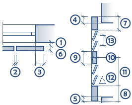
Offset to wall / Spacing / Lateral overlap: you can enter values as shown in the graphics above (1-5).
Opened by %: you can enter a percentage by which the folding shutters are open.
The following parameters change with the type you select.
Solid
Thickness: you can enter the Thickness (6) for folding shutters of the solid type.
Frame
You can enter the dimensions (6-8) for the frame of the folding shutters.
You can see the dimensions in the graphics above.
Create traverse: if you select this option, the program creates a traverse and you can enter the dimensions 9 to 11 in the Traverse area (see graphics).
Panel
Thickness: you can enter the thickness (4) of the panel for folding shutters of the Panel type.
Slats
You can enter the Thickness, Width, Angle (12) and Offset (13) for the slats of the folding shutters.
You can see the dimensions in the graphics above.
Adjusted to slats: this option applies to the Offset parameter (13). If you have selected the Adjusted to slats option, the program will ignore the offset set if it prevents the upper slat from being created completely. In this case, the program always chooses the offset in such a way that it can create complete slats.
You can find detailed information on the following tabs here:
You can find the following tools at the bottom of the palette:
Note: When you place or select a SmartPart, an arrow appears in the middle of the SmartPart, indicating the outside of the SmartPart. Depending on the position of the SmartPart within the opening, you can see another symbol, indicating that the SmartPart is mirrored before it is placed. You can set the size and color of these symbols using the Size of CursorTips for snap points and Color of CursorTips options you can find in the ![]() Options (Default toolbar), Point snap page, Point snap representation area.
Options (Default toolbar), Point snap page, Point snap representation area.
| (C) Allplan GmbH | Privacy policy |
