![]()
![]()
|
|
|
Task group for describing the processes of the balanced cantilever construction
See TRAVELER/INSTSEG for a detailed input description of this task.
With this task all loads which occur within one cycle of the balanced cantilever construction can be considered. This includes the self-weight of the form traveler as well as the weight of the (yet inactive) segments to be erected. Between the particular times of the load application the time-dependent effects (creep and shrinkage) are respectively considered.
In this sense, the task group consists of two subordinated tasks TRAVELER (form traveler) and INSTSEG (install segment).
The task TRAVELER considers the application and the removal of the weight of the form traveler at the times defined by the user.
The task INSTSEG includes the weight of the segment to be installed which is not yet connected to the structure (e.g. wet concrete in the formwork) which acts onto the active structure via the form traveler. The times of applying the weight (pouring) and removing (segment becomes part of the active structure) are defined by the user.
To accurately consider both tasks, the geometric data of the form traveler (weight, dimensions) is defined in advance as placement by the user.
These two task intertwiningly reflect the following sequence of calculation actions:
Step |
Task |
Time |
Subtask |
Load case name |
Meaning Load case name |
1 |
Apply traveler self-weight |
t1 |
TRAVELER |
TRWi-[placement]-0 TRWi-[placement]-1 |
TRW... traveler weight i... index in case of several travelers (empty, 1, 2, 3, etc.) [placement]... name of the placements 0/1... position (begin/left side or end/right side) |
|
Creep & shrinkage |
t1 |
|
CS (by default) |
|
2 |
Apply inactive segment weight |
t2 |
INSTSEG |
TRLi-[placement]-0 |
TRL... traveler load otherwise as above |
|
Creep & shrinkage |
t2 |
|
CS (by default) |
|
3.1 |
Remove inactive segment weight |
t3 |
INSTSEG |
TRL-REMi-[placement]-0 TRL-REMi-[placement]-1 |
TRL-REM... traveler load remove otherwise as above |
3.2 |
Activate segment and calculate self-weight |
t3 |
INSTSEG |
SW (by default) |
|
3.3 |
Apply prestressing |
t3 |
INSTSEG |
PT (by default) |
|
|
Creep & shrinkage |
t3 |
|
CS (by default) |
|
4 |
Remove traveler weight |
t4 |
TRAVELER |
TRW-REM-[placement]-0 TRW-REM-[placement]-1 |
TRW-REM... traveler weight remove otherwise as above |
|
Creep & shrinkage |
t4 |
|
CS (by default) |
|
The particular loads are also considered within the respective summation load cases (by default SW-SUM, SDL-SUM, PT-SUM, CS-SUM, SUMTOT), whereby the loads of the self-weight of the form traveler (TRW) are considered within the summation load case SDL-SUM and the loads of the self-weight of the segments (TRL) within the summation load case SW-SUM.
The calculation sequence can schematically be illustrated as follows:
Step 1: Apply self-weight of form traveler (time t1)
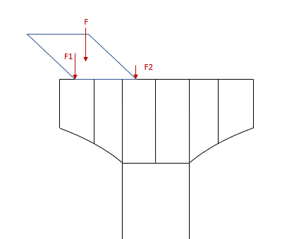
The weight force F is applied at the two anchoring points by means of the forces F1 and F2 onto the existing structure. The weight of the form traveler required for the calculation as well as its geometric definitions required for the calculation of the eccentricities are retrieved from the respective placement. The assemblies assigned to the task TRAVELER define the possible range for the application of the forces. The forces F1 and F2 are each calculated by the load type LOADFE (point load with eccentricity on element).
Step 2: Apply weight of inactive segment (time t2)
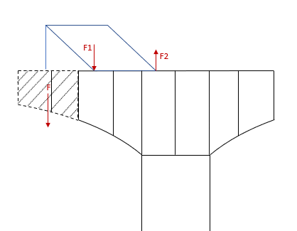
The force weight F of the inactive segment (yet not connected to the structure) is applied via the two anchoring points of the form traveler by means of the forces F1 and F2 onto the existing structure. The information required for defining/calculating the load of the forces F1 and F2 is retrieved from the placement defined in the task TRAVELER (Step 1) and from the assemblies defined there (load type LOADFE analogously to Step 1). The assemblies assigned to the task INSTSEG define the (yet inactive) elements to be erected (multiple selection possible) which are required for calculating the force F. The load application point is also defined by the placement of the task TRAVELER (Step 1).
Step 3: Remove weight of inactive segment / Activate segment & calculate self-weight / Apply prestressing (time t3)
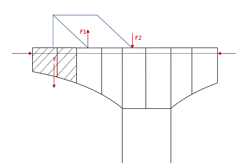
The loads F1 and F2 of the inactive segment applied via the anchoring points in Step 2 are removed from the structure by the load type LCREF (previously calculated load case with factor -1).
The respective elements are activated (INSTCONC) and their self-weight F is calculated (as part of the existing structure) (LCSELF) - corresponds to the task CONCRETE.
The tendons to be stressed in this cycle step must also be assigned to the task INSTSEG by assemblies (TSTRESS/LCSTRESS/TGROUT) - corresponds to the task TENSION.
Step 4: Remove self-weight of form traveler
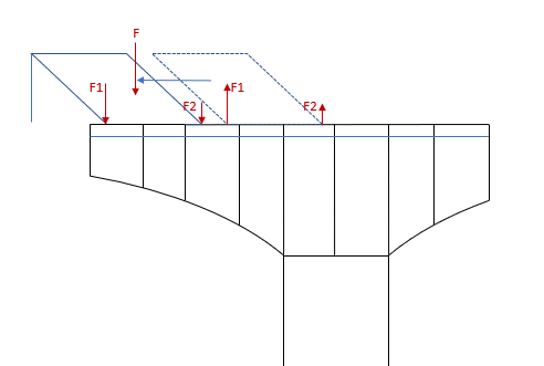
The loads F1 and F2 of the self-weight of the form traveler applied via the anchoring points in Step 1 are removed from the structure by the load type LCREF (previously calculated load case with factor -1) (on the right).
This completes one cycle of the task group CANTILEVER, and by performing the same task another time for the next cycle step the form traveler is applied again at the next position (on the left) (corresponds to Step 1 of the next cycle). Thus, the moving of the form traveler and thus all construction steps can continuously be simulated until the closure procedure.
That means in case of a symmetric construction sequence that the task group CANTILEVER must be performed for each side individually. Even if this can only be performed consecutively in the construction schedule, the particular calculation tasks can be sorted and calculated in the correct chronological sequence due to the definition of the (same) times in the two task groups.
Note: In the calculation log you can see and check all performed calculation steps, such as the calculated forces and eccentricities for the form traveler.
|
(C) ALLPLAN GmbH |
Privacy policy |
