![]() 'Data creation' tab
'Data creation' tab
This is where you set which data blocks are to be created.
Whether or not the parameters apply depends on the driver used:
Plotter
PAL, BAH, OS9, ASC, HP_
Cross shutters
PAL, BAH, OS9, ASC, HP_
Longitudinal shutters
PAL30, BAH30, ASC
Oiler
PAL, BAH, OS9, ASC, UNI
Cross bars
PAL, BAH, OS9, ASC, UNI, PRO, SOM
Cross bars robot
PAL, BAH, OS9, ASC, UNI
Longitudinal bars
PAL, BAH, OS9, ASC, UNI, PRO, SOM
Longitudinal bars robot
PAL, BAH, OS9, ASC, UNI
Meshes and stirrup meshes
PAL30, BAH30
System for welding meshes
ASC40
Girders
PAL, BAH, OS9, ASC, UNI
Girder robot
PAL, BAH, OS9, ASC, UNI
Fixtures
PAL30, BAH30, ASC, UNI
Concrete spreader
PAL, BAH, ASC, OS9
Contract data
PAL30, BAH30
![]() 'Driver' tab
'Driver' tab
Driver name:
Name of the configuration file used by the EXE file of the driver.
IF generator name:
Driver name for the IF generator used. Only required for LEIT2000.
Production data path:
The machine control files are saved to the folder or drive you enter here. Enter e.g. A:\ if the files are saved to a floppy disk. You can specify any path including network paths. If the folder does not exist, the program creates it.
If you use the [prj] string in the production data path, this string is replaced by the name of the production data file (name of *.dat file) while the NC generator is running. The conventions based on which production files are named is specified in the configuration for production data transfer.
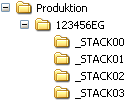
Include the _STACK00 string in the production data path to save the data in a folder which gets the name of the stack number of the relevant element. The string must be preceded by an underscore (“_") and “STACK” must be written using uppercase letters. You can enter any 2-digit number at the end, e.g. "_STACK00 “. While the NC generator is running, an initialization folder with the same name is generated. The AUFTR.DAT file is created in this folder. Then the 2-digit number is replaced by the stack number of the element (2 digits) and the files of the relevant element are stored there.
Example:
Production data path: P:\Production\[prj]\_STACK00
Name of DAT file: 123456EG.dat
Destination path: |
|
Graphical display:
None, 1D, 2D, 3D, Demo
Graphical display of panels on pallet.
Note: The elements displayed graphically by the NC generator are not (!) suitable for checking production data as these graphics may differ from the bars, girders, fixtures, .... that are actually saved in the production files. In particular, it can happen that bars, girders, fixtures, .... are not saved in the production files although they are displayed.
Tip: The range of graphical display options on the monitor can indicate to you the selected driver: If you need to use different drivers (e.g. reinforcement machine and plotter when using floppy disks) you set the appropriate display. This means you know immediately which driver is being used.
Acoustic signal:
If you enter yes, the program will beep when the data is ready.
Transferring the pallet number:
3-digit, 2-digit, pallet ID:
In plants with double wall production facilities a code is added to the pallet number to differentiate between the pallets: Thus e.g. pallet No. 1 is transferred as 101 when it is used for slab elements or wall leaf 1 elements, or as 201 when it is used for wall leaf 2 elements. This 3-digit transfer of the pallet number is considered as the default setting. However, in individual cases it is necessary to reset for 2-digits if the machine is not designed to do this.
Pallet ID: the unique pallet loading number is used. Otherwise, the pallets are numbered consecutively.
![]() 'Element manipulation' tab
'Element manipulation' tab
Fitted panels. if...
- Num. corners > 4:
This where you can specify that a panel element is to be a fitted panel if it has more than four corners.
...there are sloping edges:
This where you can specify that a panel element is to be a fitted panel if it has sloping edges.
...panel width < pallet width:
This where you can specify that a panel element is to be a fitted panel if it has a width less than the pallet on which it is to be placed.
Note: The code for fitted panels is only relevant to NCGASC, NCGPAL and NCGBAH drivers.
Consider special production flag:
No, move, code, move+code
Move panels of leaf I/ II
No, bottom, top
For Unitechnik, if required by construction restrains (wall elements – tilting, etc.).
Attention: The program moves the panels without issuing a confirmation prompt.
Move panels to start/end of pallet:
No, leaf I, leaf II, leaves I+II
Special parameter for wall panel production: to save cross shutters it is possible to load the pallet in such a way that leaf II is always moved to the edge of the pallet (see Pallet Loading configuration for the slab or wall program). Thus, theoretically, leaf I projects out above the edge of the pallet. This switch can be used to move leaf I back on to the pallet edge.
You can only use this option if every leaf can be individually flipped. If the whole pallet is flipped, then the function cannot be used.
Reduce panels to cross shutter width:
No, leaf I, leaf II, leaves I+II
In the case of double wall production, the first and second leaves on the pallet are always congruent. This setting reduces the panels to the cross shutter widths. However, this is only possible when the wall leaves are assembled manually.
Resort leaves II:
When the Reduce panels to cross shutter width parameter is enabled, the second leaves are moved away from the end of the pallet.
Move panels in X direction to center of pallet:
When area with panels on pallet is smaller than:
When this parameter is enabled and the area in which panels are placed is smaller than the area set (as a percentage of the pallet length), the NC generator moves the panels to the center of the pallet in order to avoid hydraulic problems. The distance between the panels does not change.
Reducing leaf I for solid walls [m]:
With double leaf solid wall elements, the first-produced leaf can be reduced for production reasons (e.g. 0.005 m ).
![]() 'Secondary driver' tab
'Secondary driver' tab
You have the option to enter a production data driver which is called by the primary driver automatically once the data has been created.
This is necessary when you have different control systems.
Enter the driver name and specify which data blocks are to be created.
See Data creation tab for a detailed description of the individual parameters.
| (C) Allplan GmbH | Privacy policy |