![]() Tool(s): Wall Element Design + Modify Design
Tool(s): Wall Element Design + Modify Design
After you have selected the walls, they are divided vertically and horizontally using the most recent settings. The palette shows the current settings. Adjust the parameters accordingly.
Please note that dividing vertical and horizontal joints automatically at the same time and taking the weight (Consider cranes and/or Maximum element weight) into account only produces useful results with walls that are rectangular in the view and that are divided at the same height. An inclined top or bottom level of the wall and/or varying element height leads to completely irregular joints.
The same applies to vertically dividing joints lengthwise in conjunction with an inclined top or bottom level of the wall (regardless of whether the weight is taken into account or not). Here, too, irregular joints are produced if the wall is divided horizontally in the inclined area.
In these cases, it is usually better to define the vertical joints manually as mandatory joints right from the start and restrict automatic division to the horizontal direction.
![]() Division parameters tab
Division parameters tab
Label
Specify the mark number for the next wall element. If you have selected only one wall, its mark number is entered. Otherwise, the next available number is proposed. You can control how mark numbers are assigned. For example, you can configure the program to begin with 101.
The largest possible mark number is 99999999.
Options for dividing length
Division option
You can specify how the walls are divided in the vertical direction. Select No division if you want to divide the selected walls only horizontally.
Note: If the program cannot find a solution because you have specified that divisions in openings are not permitted (Division in openings option is not selected), it will display an error message.
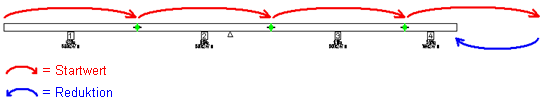
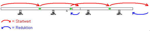
Maximum element length: depending on the visible side specified, the program creates wall elements of maximum possible length in the direction of the wall or in the opposite direction. The starting value for the length of the elements is defined by the value for the Maximum length in the Parameters for dividing length area. By incrementally reducing this starting value, the program ensures that the division criteria (maximum element weight, criteria for openings, ...) are met.
Examples of dividing walls based on maximum element length
Equal element length: divisions are calculated in the same way as for the Maximum element length option. The only difference is that the program uses the "equal element length" for the starting value.
This ”equal element length” is nothing more than the starting value the program uses to calculate the element lengths. Depending on the division criteria specified (maximum element weight, criteria for openings, ...), the actual element lengths can be shorter.
Switch start point
Mirrored version of a division. As openings and mandatory joints are taken into account, the mirrored version may yield a somewhat different result.
Consider cranes
If you have already defined one or more cranes and their locations using the ![]() Crane Location tool, you can select this option to include the crane parameters in the calculations of the individual panels.
Crane Location tool, you can select this option to include the crane parameters in the calculations of the individual panels.
Joint
Width
Enter the width of the vertical joint. A zero joint is created in the in-situ concrete layer of a double wall or thermal wall.
Connection filter
You can narrow down the entries that are presented for section selection. Click ![]() and clear the check boxes of the connections you want to exclude from the selection menu of the section. The connections that are actually available to you depend on the selected wall type.
and clear the check boxes of the connections you want to exclude from the selection menu of the section. The connections that are actually available to you depend on the selected wall type.
Section
Select a joint section.
Note: The manner in which division joints are formed usually depends on the production plant and may vary from plant to plant. If the default connections provided do not meet your requirements, you can have them customized for your needs. Please consult your sales engineer or our technical support team in Salzburg.
When you do so, please provide us with a precise sketch defining the joint point by point and the associated layer adjustments. If you want to define the connections yourself in the future, you can also schedule a training session.
Section height / Section thickness / Angle / Edge offset
Offset by
Angle
Offset...
Layer shortening / Breaking joints ...
Layer ... / Offset / Minus...
Layer shortening ...
Depending on the wall type and the selected joint section, you can specify a number of additional parameters. The effects of the entries are immediately displayed in the preview of the division.
Create fixtures
This parameter is only available if fixtures can be created for the selected joint section. After you have selected this parameter, the Fixtures area is displayed.
Fixtures
This area is only available if fixtures can be created for the selected joint section and you have selected the Create fixtures parameter. Select the fixture and specify how it is to be placed.
Fixture
Click ![]() in the column on the right to
in the column on the right to ![]() add new fixtures to or
add new fixtures to or ![]() remove existing fixtures from the Fixtures dialog box or to define the parameters of the fixtures in the table.
remove existing fixtures from the Fixtures dialog box or to define the parameters of the fixtures in the table. ![]() and
and ![]() take you from entry to entry.
take you from entry to entry.
Drop-in point
Define the direction of the fixture. Direction ... stands for the individual walls.
Fixture from
Specify whether the fixture is to be taken from the Allplan office path, Allplan project path, Allplan private path, a Manufacturer catalog or an Article catalog. For the first three options, you need to specify the File and Entry, and for the other two options, the Catalog, Class, Subclass (if necessary) and the Article.
Only symbol fixtures and groups fixtures are presented for selection. You can also use symbol group fixtures with shaped solids.
Distribution option
You can specify whether the fixtures are placed From the bottom level, From the top level or From the middle of the joint height.
Distribution values
You can specify whether the values for placing the fixtures are entered as Absolute values or As a % of the joint height.
Move reference point
You can enter the offset of the first fixture to the reference point specified for the Distribution option. Positive values point in the positive z direction.
Offset of fixtures
You can enter the offset of the other fixtures to the first fixture.
Parameters for dividing length
Minimum length / Maximum length
Shorter or longer elements are not created.
Maximum element weight
Specifies the maximum element weight. But you can also define one (or more) crane locations in the drawing. In this case, the program calculates the maximum element weight from the loaded radii. If the resulting weight is less than the value set, division is based on the loaded radii.
Division in openings
Select this option if divisions in openings are permitted. Otherwise, the division point is moved beside the opening by the value specified for Minimum offset to openings.
Options for dividing height
Division option
You can specify how the walls are divided in the horizontal direction. Select No division if you want to divide the selected walls only vertically.
Same height: starting at the wall base, the program divides the wall in elements of the same height, which you can specify using the Element height parameter.
If the height of the element at the top is not exactly the Element height specified, the program uses the remaining height to create this element.
Different height: first you need to specify the number of divisions you want to create. Click ![]() to open the table for the Division parameter. You can add more columns by clicking
to open the table for the Division parameter. You can add more columns by clicking ![]() Add. To delete existing columns, select the columns and click
Add. To delete existing columns, select the columns and click ![]() Remove. Specify the Element height.
Remove. Specify the Element height.
If there are several divisions, you can use ![]() and
and ![]() to switch between the columns of the table and change the Element height directly in the dialog box.
to switch between the columns of the table and change the Element height directly in the dialog box.
If the height of the element at the top is not exactly the last height you specified, the program uses the remaining height to create this element. If the sum of the element heights exceeds the wall height, the program only considers the values specified for the current wall height. Here, too, the remaining height is used for the element at the top. This height may differ from the value specified.
Joint section
Select a joint section. The list box includes all the entries of the joint section catalog that are assigned to the current factory and that can be used with the existing wall thickness.
Joint width
Enter the width of the horizontal joint.
| (C) Allplan GmbH | Privacy policy |