![]() Module(s): Catalogs
Module(s): Catalogs
You can use this catalog to define defaults for the generation of production data using the ![]() Production Data/NC Generator tool.
Production Data/NC Generator tool.
![]() 'Data creation' tab
'Data creation' tab
Created on:
Date of creation of the data record.
Last modified:
The most recent modification date.
Name:
User-defined name, which is displayed in the list box for driver selection in the NC Generator dialog box.
Description:
User-defined name, which is displayed for information at bottom right on the Driver/order data tab in the NC Generator dialog box.
Driver:
Selection of UNITECHNIK driver, which is displayed for information at bottom right on the Driver/order data tab in the NC Generator dialog box.
If you want to create the data in PXML format, select the ProgressXML entry.
Coding:
In accordance with the interface, the file is to be created using ASCII coding. If you want, you can also create it using ANSII code. However, you should agree in advance with your data exchange partner on which one you are going to use.
Graphical display of output:
2D, 3D
You can specify how elements are displayed in the window at top right in the NC Generator dialog box.
Tip: The range of graphical display options on the monitor can indicate to you the selected driver: If you need to use different drivers, you set the appropriate display. This means you know immediately which driver is being used.
Production data path:
The machine control files are saved to the folder or drive you select or enter here. You can enter any path, including network paths. If the folder does not exist, the program creates it.
File names:
Convention based on which file names are created.
Pattern: enter the desired name. Formatting characters are used as placeholders for variable values. The program replaces the formatting characters with the corresponding values. Enter the formatting characters as follows:
%s: for strings
%d: for integers
%f: for floating point numbers
You can also define how strings and numbers are output:
%10s: output of 10 characters minimum (with blanks).
%-10s: as above, left-aligned.
When you enter a point (".") between "%" and the number, the resulting string is truncated to the number specified.
For example, entering %.4s changes the "1234567" string to "1234".
%3d: output of 3 characters minimum (with blanks).
%03d: as above; however, zeros (e.g. 002) are added.
%.3f: output of 3 decimal places.
%6.3f: output of a total of 6 characters (including decimal point) and 3 decimal places.
Variable: Enter an arithmetical expression for each wildcard. The ',' character is used as a separator. Arithmetical expressions can be arithmetical operators, numbers and variables.
The convention based on which production data files (PrdNam) are named is specified in the configuration for production data transfer.
If you use the StkIdx variable to define the file name, the program creates as many files as you have defined for the Factor parameter (provided the factor of the structural precast element, i-Part is greater than 1). You can specify the Factor for structural precast elements, i-Parts on the Invoicing tab of the palette. The StkIdx variable runs through all the values: from 1 up to the factor.
Otherwise, the StkIdx variable is set to 1 and only one file is created.
![]() 'Mirroring/structure' tab
'Mirroring/structure' tab
You can define the following parameters for the element selected in the list on the left.
Data structures
All elements with the exception of sandwich walls and Iparts:
These elements are always created in the default structure. Two files are created for double walls and thermal walls: one for first production (leaf 1) and another one for second production (leaf 2). The insulating layer is transferred as a surface fixture (provided a reference fixture is defined in the insulation material catalog). The outline of the insulating layer is obtained from the outlines of the layers.
Except for half floors, double walls and thermal walls, you can add 3D data to these default structures. This data is not in accordance with the current requirements of the interface. You need to discuss this issue with your data exchange partner in advance.
Sandwich wall:
Default: Unitechnik default structure (see interface definition). This means that the multi-layer element is written to a single file. The layers are filled out in the SLABDATE block. All the leaves are transferred to the CONTOUR blocks. The outlines of the panel parts that are not on the formwork are given the "special formwork" edge attribute.
Layer/lot: Unitechnik layer/lot structure (see interface definition)
The layers/lots are determined based on the thickness of the layers. If the thickness of a layer is greater than that entered (for example, at corner connections), additional lots of the corresponding thickness are created. This is an independent algorithm that cannot be controlled by the user. As there are no requirements on the part of customers, we cannot make a statement concerning the quality of the data and of the algorithm.
3D polyhedron: default structure; 3D data is created in addition to the geometric data in 2D. This data is not in accordance with the current requirements of the interface. You need to discuss this issue with your data exchange partner in advance.
IParts:
Default: Unitechnik default structure (see interface definition)
Layer/lot: Unitechnik layer/lot structure (see interface definition)
By default two layers are created for each structural precast element. The bottom layer contains the lowest area of the precast element and the component thickness of the entire element as a lot (outline). The lowest area must be flat on the formwork, that is the direction vector must be perpendicular to this area.
In addition, a layer with a thickness of 0 is transferred. This layer contains the topmost area of the element.
You can specify your own cutting planes using Z coordinates. In this case, the element is cut at the Z height specified and the area cut is transferred as a layer. The thickness is measured at the height of the cutting planes.
A further division into lots is currently not implemented. A lot always contains all the polylines as an outline. These polylines result from the cut at the corresponding height.
Based on the Z coordinates, fixtures and bar reinforcement are assigned to the corresponding layers. This is necessary for leveling and cutting systems. All other elements (lattice girders, attached reinforcement and so on) are transferred in the first layer.
3D polyhedron: default structure; 3D data is created in addition to the geometric data in 2D. This data is not in accordance with the current requirements of the interface. You need to discuss this issue with your data exchange partner in advance.
Mirroring coordinates
None, x direction, y direction, x+y directions
You can mirror the coordinates of the individual elements. This also defines the origin from which the coordinates are measured.
Pallet width for calculation of y offset when mirroring:
When data is transferred by panel, this offset is used to calculate leaf 2.
![]() 'Element data' tab
'Element data' tab
Element name:
The mark number or mark number text is written to the interface to ensure that the element can be identified uniquely in a database.
Bar overlap:
As entered: The bar overlaps are taken from the reinforcement entered. The bar overlaps do not necessarily have to match the actual bar overlaps, for example, when you modify the reinforcement later.
Calculate: The bar overlaps are calculated from the actual reinforcement (including basic and additional reinforcement, lattice girders, stirrup cages and so on).
Write project coordinates:
The coordinates in plan are used to transfer the positions of the elements in compliance with the Unitechnik interface.
Please note that some control computers may nor permit negative values.
This has been the default setting since version 6.
Overwrite product codes
You can freely define the product codes (for example, 0 for half floor) that are specified in the interface. Each precast element type can be given its own product number. Do the following:
To delete a product number, select the assignment in the list and click the Delete button.
Note: A structural precast element always consists of an exact type (for example, IPart - column) and a general type (IPart). When you use the general type, this type applies to all structural precast elements. If there is an additional assignment for a special type, this assignment has priority over the general type.
If there are several assignments for a type, the first assignment is always used.
![]() 'Geometry' tab
'Geometry' tab
Remove points on continuous lines:
Points on straight lines are removed.
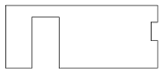
Element geometry encloses recesses at panel edge:
If this check box is selected, recesses at the edge of an element are not blended with the outline of the element; i.e. the element's original outline is retained.
Important: If you create an architectural opening that projects beyond the element, the element is enlarged by the projecting opening!
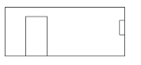
Otherwise, the outline will look like this:
Consider protruding parts with max. element size
The maximum element size is recalculated for protruding parts of the selected type; the coordinates of the data are also recalculated. The parameters of the fixture catalog are used for fixtures.
Bar reinforcement must penetrate the element edge so that the element dimensions are enlarged! In other words, a cranked bending shape that projects beyond the panel edge has no effect on the element size!
![]() 'Line attributes' tab
'Line attributes' tab
Add edge attribute (bit 2) to poured joints at wall ends:
In the case of poured joints at concrete wall ends, poured joint attributes can be added to these panel edges.
If this check box is not selected, the poured joint bit is not set. Otherwise, the following options are available:
Add only: poured joint bit is set; chamfer attributes as transferred from Allplan
Set chamfer: poured joint bit is set; top and bottom chamfer attributes are set explicitly (Uni bit mask = 0004, unless other bits are set in addition)
Delete chamfer: poured joint bit is set; top and bottom chamfer attributes are deleted explicitly (Uni bit mask = 000D, unless other bits are set in addition)
Attribute manipulation
You can use this option to manipulate specific edge attributes. In other words, you can set an attribute to a specific value that is not available in the CAD program. There are three lines you can use to define the attributes that are to be detected and replaced with different values.
Explanation of the individual fields:
The attributes and bit masks are entered in decimal notation in the mask.
|
Bit number |
Description |
Decimal |
Hex |
|
0 |
No chamfer at bottom |
1 |
0x01 |
|
1 |
Special formwork |
2 |
0x02 |
|
2 |
Poured joint |
4 |
0x04 |
|
3 |
No chamfer at top |
8 |
0x08 |
|
4 |
Rounding off at bottom |
16 |
0x10 |
|
5 |
Spring |
32 |
0x20 |
|
6 |
Groove |
64 |
0x40 |
|
7 |
Rounding off at top |
128 |
0x80 |
(The attributes are specified in hexadecimal notation in the interface.)
Example of attribute manipulation
![]() 'Wall panel' tab
'Wall panel' tab
Edges consist of smooth edge + groove / smooth edge + tongue / groove + tongue / smooth edge + groove + tongue
When a groove and/or tongue is not applied to the entire section edge of a wall panel, the settings you make here are used to transfer this edge to production.
![]() 'Fixtures' tab
'Fixtures' tab
Create fixture data:
You can configure the program not to create any fixture data at all.
Fixture name:
Specify whether the reference text or list text is to be used. This depends on the method your data exchange partner uses to analyze the data. The other name, which is not used, is displayed in the info text.
Create wall upstands as fixtures:
Architectural upstands of walls can be transferred as separate fixtures. You can define the name of the fixture freely or select it from the fixture catalog using the list box. In the latter case, the values specifying the "type and code" are also taken from the catalog and entered correctly.
Please bear in mind that upstands around corners or 3D geometries cannot be displayed exactly as fixtures in the Unitechnik interface are merely defined by a polygon consisting of a value for the Z dimension and another one for the thickness.
Create poured joints as fixtures:
Poured joints in walls can be transferred as separate fixtures. You can define the name of the fixture freely or select it from the fixture catalog using the list box. In the latter case, the values specifying the "type and code" are also taken from the catalog and entered correctly.
Please bear in mind that 3D geometries cannot be displayed exactly as fixtures in the Unitechnik interface are merely defined by a polygon consisting of a value for the Z dimension and another one for the thickness.
Create shuttering objects as fixtures:
Shuttering objects can be transferred separately as fixtures. You can define the name of the fixture freely or select it from the fixture catalog using the list box. In the latter case, the values specifying the "type and code" are also taken from the catalog and entered correctly.
Please bear in mind that 3D geometries cannot be displayed exactly as fixtures in the Unitechnik interface are merely defined by a polygon consisting of a value for the Z dimension and another one for the thickness.
Create stirrup cages as fixtures:
Min-max boxes of stirrup cages can be transferred as separate fixtures. This makes it easier for the control computer to check for collisions with other components as the exact position of bent reinforcing bars is not always defined clearly by the Unitechnik interface.
You can define the name of the fixture freely or select it from the fixture catalog using the list box. In the latter case, the values specifying the "type and code" are also taken from the catalog and entered correctly.
Create lattice girders as fixtures:
Lattice girders are transferred as fixtures. You can reference an entry in the fixture catalog or define the name freely. When you use a catalog reference, some parameters are automatically taken from the catalog (name, type and code, info text).
The geometric data (for the plotter or laser) is created as follows:
Girder marker length: the length of the girder is only indicated, that is the length of the markers at the start and end of the girder. 0 prints the whole girder.
Indicate girder width (bottom boom): a slash is used to indicate the width of the girder on the side of the bottom boom.
Create in second leaf: the lattice girder is created so that the bottom boom is in the second leaf.
![]() 'Reinforcement' tab
'Reinforcement' tab
Create reinforcement data:
You can configure the program not to create any reinforcement data at all.
Longitudinal bars at bottom, Longitudinal bars at top, Cross bars at bottom, Longitudinal bars at top, 1st/2nd/3rd diameter:
You can mark the corresponding bars of the basic reinforcement as 'producible' or 'non-producible'. In any case, the data is created. Deactivated means that the bars are marked with the "manual production flag" in the interface. In this case, the control computer does not transfer the bars to the machine, and you have to cut and place them manually. The data is then mainly used for materials management.
Free bars:
You can mark free bars of attached reinforcement as 'producible' or 'non-producible' (see above).
Additional bars at bottom, Additional bars at at top:
You can mark additional bars of the reinforcement at bottom and top as 'producible' or 'non-producible'.
Core reinforcement:
You can mark core reinforcement of a thermal wall with an in-situ concrete core as 'producible' or 'non-producible'.
Additional stirrups:
You can mark additional stirrups (longitudinal stirrup bars) of a stirrup cage or bent-up mesh as 'producible' or 'non-producible'.
Stirrup bars:
You can mark stirrup bars of a stirrup cage as 'producible' or 'non-producible'.
The With bending data setting means that bending blocks are generated in addition to the data of the length before bending. Machines use these bending blocks for bending.
Additional bent reinforcement:
You can mark free additional bent reinforcement (from the Engineering modules) as 'producible' or 'non-producible'.
The With bending data setting means that bending blocks are generated in addition to the data of the length before bending. Machines use these bending blocks for bending.
![]() 'Filter' tab
'Filter' tab
Non-producible bar types, diameters, bar lengths:
These are bar types, diameters and bar lengths that are not produced in accordance with the configuration.
Write: the bars are given the No automatic production identifier in the Unitechnik file.
If you do not select this option, the bars are not written to the file.
BVBS: an additional BVBS file is created for each element of the non-producible bars. Thus the bars can be produced separately by a machine. The name of the file is identical to that of the Unitechnik file and the extension is *.abs.
Warning: if the element includes a non-producible bar, a warning is displayed in the dialog box of the NC generator.
Filter by diameter, length
Producible diameters [mm]:
The diameters that can be processed by the machine need to be specified separately for cross bars, longitudinal bars and additional bars.
You can enter one or more values. Example: 6, or 6,8,10, .
lengths that are not to be produced:
You can specify lengths that are not to be produced separately for cross bars, longitudinal bars and additional bars. This way you can exclude bars from production e.g., prefabricated cross bars.
You can enter one or more values. Example: 0-0.199 or 0-0.199, 2.485,
![]() 'Sorting' tab
'Sorting' tab
You can define how the bar data is to be sorted.
Sort sequence, Sorting:
Select an entry in the table on the left and edit it using the buttons to the right of the table. You can move the entry up or down, sort the entries in ascending or descending order as well as switch the criterion for sorting on and off.
Sequence numbers for bar type:
When the bars are sorted by bar type, you can specify which bar type has priority by assigning a sequence number.
To change these sequence numbers, select the number of a bar type in the list and click it once to open it for editing.
Band width for x, y coordinate:
This switches off sorting in the specified range, so that you can use the next priority if there are very small differences (e.g., sloping edges).
Compress reinforcement elements:
Bars of the same length and diameter that are placed so that they are parallel to one another on a pallet are not transferred individually but using the number or distance. This considerably cuts down the volume of data e.g. by reducing 35 pieces of cross bar from 35 data blocks down to 1.
Max. spacing for division [mm]:
You can specify the maximum spacing (parallel offset) between the elements to be compressed.
![]() 'Spacer' tab
'Spacer' tab
You can specify how and for which bars spacers are calculated.
Longitudinal bars:
Spacers are calculated for the longitudinal bars.
Cross bars:
Spacers are calculated for the cross bars, layers 1 and/or 2 (bars placed manually).
Spacer type:
The spacer type is determined based on the concrete cover. You specify the type by entering a specific region (from - to). The height of the spacer is usually the type number times 5.
Example: Type 3: 0.0 - 19.0, type 4: 20.0 - 100.0
If a valid region cannot be found, spacers are not transferred.
Cross bars at top:
Spacers are calculated for the cross bars at the top, layers 1 and/or 2 (bars placed manually).
Spacer type for cross bars at top:
This type is generally transferred for the cross bars at the top.
Valid spacer diameters:
You can specify which diameters can be used with spacers. If a diameter is not in accordance with the region specified, spacers are not transferred.
Calculation method:
At the moment only the "equidistant" method is implemented!
Equidistant: the spacers are distributed evenly over the cross bars. The number of spacers is calculated from the weight of the reinforcement supported by the cross bars and the maximum load-bearing capacity of a spacer. This is used for slab elements and wall leaf 2.
Lock girders: the spacers are placed alternately to the left and right of the lattice girder. This is used for wall leaf 1.
Offset info:
Short: provides information on the spacer type, edge offset and axis offset.
Long: each spacer mark is transferred (only required if the "equidistant" method is not used!)
![]() 'Spacer parameters' tab
'Spacer parameters' tab
Special information on the spacers. The following parameters are used in accordance with the calculation method selected:
Min. number per bar, Max. number per bar:
You can have a maximum of 20.
Max. number per edge bar:
You can have a maximum of 150.
Min. edge offset:
Minimum distance between spacers and edge.
Min. offset, Max. offset:
Limits defining the spacing between the individual spacers.
Max. load capacity of a spacer [kg]:
This value has an effect on the number of spacers: the program calculates the number of spacers from the load-bearing capacity of the spacers and the weight of the reinforcement applied to a panel. When it comes to calculating the number of pieces, however, the other parameters have higher priority.
Note:
If there are too many spacers or not enough, you should change the setting specifying the load-bearing capacity first.
Min. offset to bars:
Min. offset to girder slab:
Min. offset to girder for wall leaf 1:
Min. offset to girder for wall leaf 2:
These settings are only used for the "lock girder" method.
![]() 'Bundling' tab
'Bundling' tab
Bundle:
You can specify whether the bars are to be placed in a "bundled" manner. "Bundled" means that a specific coordinate is used for the bars, which are then placed by hand.
Produce in leaf 1:
The relevant bars of leaf 2 are already transferred in leaf 1.
You can specify whether core reinforcement (reinforcement of a thermal wall with an in-situ concrete core) is produced in leaf 1, leaf 2 or whether a separate file is created. The name of tis file is obtained from the name and extension of the production data file (defined as Name on the Data creation tab) plus the additional extension *.bew.
![]() 'Placement' tab
'Placement' tab
Placing coordinates:
You can specify the placing coordinates of bundled bars in the x and y directions.
Placing height (z coordinate):
The specified height is transferred as a Z coordinate. This is important if the bundled bars are placed above the cross shutter so that the arm of the reinforcement robot is not damaged.
Set insertion angle to 0 degrees:
Normally the actual angle of the bundled bars is transferred. Selecting the Set insertion angle to 0 degrees - Yes setting recalculates the insertion angle and sets it to 0 degrees. This setting is required on some machines (Filzmoser) so that the robot can place 2 bars at once (with a double grab). However, some machines require a real insertion angle (not equal to 0 degrees) so that they can recognize bars that cannot be placed.
Insertion angle for wall / slab robot:
This setting is to inform the NC generator of the insertion angles that are valid so that bars can be bundled.
![]() 'Reinforcement system' tab
'Reinforcement system' tab
Data structure:
Leveling and cutting system: the bar data is created in accordance with the structure for leveling and cutting systems (see Unitechnik interface).
Att.reinf. + leveling, cutting: the bar data is created in accordance with the structure for attached reinforcement.
Lattice girders and reinforcing bars outside a reinforcement mesh are explicitly created outside the STEELMAT blocks in the RODSTOCK and BRGIRDER blocks.
Attached reinforcement: the bar data is created in accordance with the structure for attached reinforcement (see Unitechnik interface). Reinforcement belonging to a single mesh is combined in a STEELMAT block. However, this is only possible if the reinforcement data was created using the Optima generator.
Note: Lattice girders and reinforcing bars outside a reinforcement mesh are geometrically assigned to the mesh (based on the X/Y plane) and transfered within the STEELMAT block.
Z coordinate at bar:
Relative to STEELMAT: normally, the Z coordinates of the bars (in the RODSTOCK field) are calculated based on the Z offset of the mesh, which means that the Z value for the first bar layer is always 0 as the concrete cover is included in the mesh offset.
Absolute: using this, you can specify that the absolute Z coordinate (relative to SLABDATE) is used, which means that the mesh offset in the Z direction is 0.
Turning information:
Deactivated: the turning flag of the mesh (indicating whether the mesh has to be turned after welding) is not set.
By span direction: the turning flag of the mesh (indicating whether the mesh has to be turned after welding) is set if the span direction is >= 45°.
By element type: the turning flag of the mesh (indicating whether the mesh has to be turned after welding) is set in accordance with the element type.
Calculate MWS cross bars of layer 2 as:
In conjunction with attached reinforcement, the exact bar type is lost as you do not need to place any manual bars.
Using this setting, you can "restore" this bar type for Optima bars that are transferred in accordance with the normal structure for leveling and cutting systems.
Transfer attached stirrup cages:
Custom bending shape: bending data is transferred as a custom bending shape without special specifications for Progress. This transfer type cannot be used with Filzmoser machines.
Progress bending definition: this is a special way of transferring bending data, which makes it possible to calculate the exact bar position in 3D. This setting only applies to special systems of the Progress company (this is not an interface standard). There is a special assignment of some fields in the RODSTOCK data record and data is transferred in the BENDING DATA RECORD FOR CUSTOM BENDING SHAPES.
Default bending shape: reinforcement cages created using the ![]() MWS Reinforcement Group tool are written as a BENDING DATA RECORD FOR HOOKS to the Unitechnik data without a special extension of the RODSTOCK data record.
MWS Reinforcement Group tool are written as a BENDING DATA RECORD FOR HOOKS to the Unitechnik data without a special extension of the RODSTOCK data record.
Open the ![]() Configurations, select General, Attached Reinforcement, Stirrup cages and set the Bending shape limit parameter to Acc. to bending shapes.
Configurations, select General, Attached Reinforcement, Stirrup cages and set the Bending shape limit parameter to Acc. to bending shapes.
As the production data transferred using this option does not include any special parameters that are aligned with the Progress company, the cages must meet the following conditions:
Create mesh as:
Common stock mesh is usually not produced automatically and thus not included in the interface.
„EXTIRON" – acc. to interface: the mesh is transferred as an "external bar", which means that only the name and weight are transferred (for materials management).
„EXTIRON" – with geom./bending data: the mesh is transferred as an "external bar". In addition, a geometric data block and, if necessary, a bending data block are created. This type of transfer is not in accordance with the interface.
„STEELMAT" – acc. to interface: if the data structure for attached reinforcement is selected, you can transfer stock mesh as a "steelmat" block. The "steelmat" block does not contain any RODSTOCK data elements. It is only the size and the Z coordinate of the mesh that are included.
„EXTIRON" – with bending data: if the data structure for attached reinforcement is selected, you can transfer stock mesh as a "steelmat" block. The "steelmat" block does not contain any RODSTOCK data elements. It is only the size and the Z coordinate of the mesh that are included. In addition, a bending block for the bending shape is transferred for bent-up mesh. This type of transfer is not in accordance with the interface.
![]() 'Lattice girders' tab
'Lattice girders' tab
Produce standard girders
Produce shear girders
Produce secondary girders:
You can specify the criterion for producibility for the girders here.
Transfer dominating girder type only
If there are different girder types in a panel (e.g., shear or secondary girders), only the girder type with the greatest number is transferred to the machine so that delays caused by breaks in production are avoided.
Insertion angle for wall / slab robot:
Enter the insertion angle here. You can enter one or more values. Example: 0, or 0,90, .
Producible heights of girders:
You can exclude girders from production based on their height (as entered in the girder catalog).
The value is specified in [mm]. You can enter several values. Example: 100,120,140,160,
Non-producible lengths:
You can exclude girders from production based on their length (as entered in the girder catalog).
You can enter one or more values. Example: 0-0.199, or 0-0.199, 0.40,
![]() 'Sorting' tab
'Sorting' tab
You can define how the lattice girder data is to be sorted.
Sort sequence, Sorting:
Select an entry in the table on the left and edit it using the buttons to the right of the table. You can move the entry up or down, sort the entries in ascending or descending order as well as switch the criterion for sorting on and off.
Sequence numbers for girder type:
When the girders are sorted by type, you can specify which girder type has priority by assigning a sequence number.
To change these sequence numbers, select the number of a girder type in the list and click it once to open it for editing.
Band width for x, y coordinate:
This switches off sorting in the specified range, so that you can use the next priority if there are very small differences (e.g., sloping edges).
Compress girder data:
Girders of the same length and diameter that are placed so that they are parallel to one another on a pallet are not transferred individually but using the number or distance. This considerably cuts down the volume of data e.g. by reducing 10 pieces of secondary girders from 10 data blocks down to 1.
Max. spacing for division [mm]:
You can specify the maximum spacing (parallel offset) between the elements to be compressed.
| (C) Allplan GmbH | Privacy policy |

