![]()
![]()
|
|
|
Define and calculate a global horizontal area load on the structural members assigned to this load by assemblies
In longitudinal direction the load is applied orthogonally to the element/beam axis, which results from the connection of the centers of gravity of the cross sections of the loaded elements.
The area load is defined by the load magnitude q. The vertical “load length” for the application of the load can automatically be evaluated on the basis of the defined cross section. The load can be applied on a cross section part differently from the structurally effective cross section (e.g. curbs) using the input of uload by means of the structural unit of the type load. Further, a user-defined load length can be defined by the input of leff.
Also, the position of the load application point can be defined by the input of pos.
Arguments
uload
Number of the structural unit of the type load, whose assigned boundary area should be taken into account for evaluating the load length in vertical direction.
For this evaluation a “bounding box” (minimum bounding rectangle) is placed, whose sides are parallel to the coordinate axes of the cross section. The largest vertical side determines the load length in y-direction by size (length) as well as by position.
Note: A user-defined load length can be defined by the input of leff.
In both cases the load application point is positioned at the midpoint of the load line.
Note: The position of the load application point can be moved by the input of pos.
Note: The input of uload is ignored, if the position pos and the length leff is defined.
q
Magnitude of the area load [force/area] (positive values for loads in the direction of the positive local z-axis of the elements)
If the definition of the load is done by q (without uload) only, the boundary lines of the cross section are taken into account for evaluating the load length in vertical direction. For this evaluation a “bounding box” (minimum bounding rectangle) is placed, whose sides are parallel to the coordinate axes of the cross section. The largest vertical side determines the load length in y-direction by size (length) as well as by position.
If no other parameters are defined, the load is applied with a constant magnitude at the midpoint of the load length along the element/beam axis.
Note: If the input of uload is defined, the load length is taken as described there.
Note: If the input of leff is defined, the load length is taken from there.
Note: The position of the load application point can be moved by the input of pos.
qe
Magnitude of the area load at the end of the loaded elements in longitudinal direction [force/area]
qm
Magnitude of the area load in the middle of the loaded elements in longitudinal direction [force/area]
pos
Definition of the load application point
The load application point is always positioned in the midpoint of the load length.
If this input is missing, the position results from the automatic evaluation of the load length.
Optionally, the load application point can be moved to an arbitrary defined reference point by the input of its name.
The center of gravity of the cross section area of the loaded elements can be used by inputting COG.
Note: If pos is defined, also leff or uload must be defined.
leff
Effective load length
Define a load length differently from the automatically evaluated one for the input of q and uload
The load application point is always positioned at the midpoint of this length.
The position remains unchanged as defined due to pos.
A special case occurs, if a load length leff is defined without defining the position by pos. In this case the structural node is taken as the load application point.
|
SUMMARY and OVERVIEW
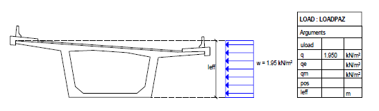
1. Load applied directly to the cross section (only q)
Arguments |
Input |
uload |
No input |
q |
0 or value Magnitude of the load at the load begin in longitudinal direction of the loaded elements |
qe |
0 or value Magnitude of the load at the load end in longitudinal direction of the loaded elements |
qm |
0 or value Magnitude of the load in the middle of the load in longitudinal direction of the loaded elements |
pos |
No input: Position due to the autom. evaluation of the load length OPTIONAL: Definition of a different load application point (then leff is required in addition) 1. Input the name of a reference point 2. COG for the center of gravity of the cross section of the loaded elements |
leff |
No input: Automatic evaluation of the load length OPTIONAL: Value |
|
|
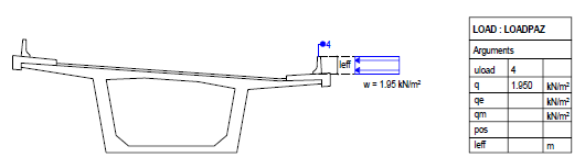
2. Load defined by structural unit of the type load (uload)
Arguments |
Input |
uload |
Number of the structural unit of the type load |
q |
0 or value Magnitude of the load at the load begin in longitudinal direction of the loaded elements |
qe |
0 or value Magnitude of the load at the load end in longitudinal direction of the loaded elements |
qm |
0 or value Magnitude of the load in the middle of the load in longitudinal direction of the loaded elements |
pos |
No input: Position due to the autom. evaluation of the load length OPTIONAL: Definition of a different load application point (only applicable, if leff is not defined) 1. Input the name of a reference point 2. COG for the center of gravity of the cross section of the loaded elements |
leff |
No input: Automatic evaluation of the load length OPTIONAL: Value |
|
|
EXAMPLE / TYPICAL APPLICATIONS
Example 1: Wind on superstructure: Constant uniform load applied directly to the cross section
Arguments |
|
q |
Value |
|
|
Example 2: Wind on equipment Load applied by structural unit 4 of the type load
Arguments |
|
uload |
4 |
q |
Value |
|
|
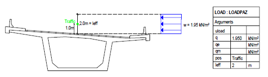
Example 3: Wind on traffic with 2 m height Load eccentrically at the reference point “Traffic” (1 m above roadway surface level)
Arguments |
|
q |
Value |
pos |
Traffic |
leff |
2 |
|
(C) ALLPLAN GmbH |
Privacy policy |