![]()
![]()
|
|
|
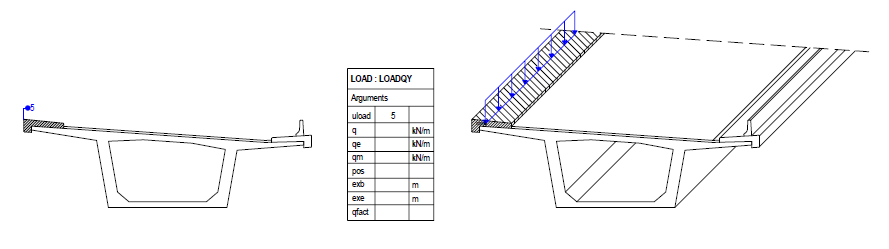
Define and calculate a global vertical line load on the structural members assigned to this load by assemblies
In longitudinal direction the load follows the “load line”, which results from the connection of the load reference points of the cross sections of the loaded elements.
The line load can be defined directly by the load magnitude q or automatically be calculated by the input of uload by means of the structural unit of the type load.
Arguments
uload
Number of the structural unit of the type load, whose assigned boundary area should be applied as load over the length
The load reference point is per default the center of gravity of the assigned area.
By the input of pos a different reference point can be defined.
Further, the parameters exb and exe can optionally be defined for this input.
Note: This input is ignored, if the load magnitude is defined by q, qe or qm.
q
Magnitude of the line load [force/length] (positive values for loads in the direction of the negative global Y-axis)
If no other parameters are defined, the load is applied with a constant magnitude along the load line (constant line load).
Note: If this value is defined, a possibly defined input of uload is ignored.
qe
Magnitude of the line load at the end of the load line (e.g. trapezoidal or triangular load) [force/length]
Note: If this value is defined, a possibly defined input of uload is ignored.
Note: This input is ignored, if the expression qfact is defined.
qm
Magnitude of the line load in the middle of the load line (parabolic load curve!) [force/length]
Note: If this value is defined, a possibly defined input of uload is ignored.
Note: This input is ignored, if the expression qfact is defined.
pos
Definition of the load reference point
If this definition is missing, the structural node is taken per default when using q, qe or qm (when using uload as described there).
An arbitrary defined reference point can be referenced by inputting its name.
The center of gravity of the cross section area of the loaded elements can be used by inputting COG.
exb
Eccentricity of the load begin in longitudinal direction [length]
Distance in the direction of the load line from the begin of the loaded structural member (point 1) to the begin of the line load (point 2)
Important note: The distance (from point 1 to point 2) is dependent on the direction and is defined with positive or negative sign in relation to the direction of the stationing, i.e. positive in positive direction of the stationing and negative in negative direction of the stationing.
exe
Eccentricity of the load end in longitudinal direction [length]
Distance in the direction of the load line from the end of the loaded structural member (point 1) to the end of the line load (point 2)
Important note: The distance (from point 1 to point 2) is dependent on the direction and is defined with positive or negative sign in relation to the direction of the stationing, i.e. positive in positive direction of the stationing and negative in negative direction of the stationing.
qfact
Factor or expression to be applied to q (multiplication).
The expression can be used in the same way as when defining a formula and thus contain constant values or mathematical expressions and tables dependent on the stationing.
qeff = q * qfact or qfact(s)
Note: If this expression is defined, a possibly defined input of qe and qm is ignored.
mass Option to mark this load definition for being considered as mass within the calculation of the eigenvalues (see EIGEN). |
SUMMARY and OVERVIEW
1. Load defined by structural unit of the type load
Arguments |
Input |
uload |
Number of the structural unit of the type load |
q |
No input (otherwise uload is ignored) |
qe |
No input (otherwise uload is ignored) |
qm |
No input (otherwise uload is ignored) |
pos |
No input: reference point = center of gravity of the assigned cross section area of the structural unit OPTIONAL: Definition of a different reference point 1. Input of the name of the reference point 2. COG for the center of gravity of the cross section of the loaded elements |
exb |
OPTIONAL: Input of the eccentricity at the begin |
exe |
OPTIONAL: Input of the eccentricity at the end |
qfact |
No input (ignored, if defined) |
|
|
2. Load defined by q, qe, qm
Arguments |
Input |
uload |
No input (ignored, if defined) |
q |
0 or value Load magnitude at load begin |
qe |
0 or value Load magnitude at load end |
qm |
0 or value Load magnitude in the middle of the load |
pos |
No input: Reference point = structural node of the loaded elements OPTIONAL: Definition of a different reference point 1. Input of the name of the reference point 2. COG for the center of gravity of the cross section of the loaded elements |
exb |
OPTIONAL: Input of the eccentricity at the begin |
exe |
OPTIONAL: Input of the eccentricity at the end |
qfact |
OPTIONAL: Input a factor or function (qe, qm are ignored, if defined) |
|
|
EXAMPLES:
Example 1: Constant uniform load over the whole length of the member
Arguments |
|
q |
Value |
|
|
Example 2: Constant uniform load, begin: 2 m after begin of member, end: 3 m before end of member
Arguments |
|
q |
Value |
exb |
2 |
exe |
-3 |
|
|
Example 3: Triangular load over the whole length of the member (increasing in the direction of stations)
Arguments |
|
q |
0 |
qe |
Value |
|
|
Example 4: Trapezoidal load over the whole length of the member
Arguments |
|
q |
Value 1 |
qe |
Value 2 |
|
|
Example 5: Load applied by structural unit 2 of the type load
Arguments |
|
uload |
2 |
|
|
Example 6: Load by function
Arguments |
|
q |
Value |
qfact |
sin($s) |
TYPICAL APPLICATIONS
Case 1: Superimposed dead loads, e.g. curbs
Remark: Position of the structural unit irrelevant, load application point = center of gravity of the boundary area (curb)
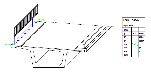
Case 2: Superimposed dead loads, e.g. railings
Remark: load application point = position of the reference point “Railing”
|
(C) ALLPLAN GmbH |
Privacy policy |
