You can change the dimensions and characteristics of all steel and timber elements.
Most parameters listed here are for the Rafters tool. You can define the parameters for the other elements in the same way.
This section also mentions special features of other elements.
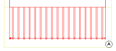
Eaves/ridge shape (for rafters, hip/valley rafters)
![]()
![]()
Select the manner in which the rafters end at the ridge and eaves
Cross-section (general)
Width/height |
This is where you enter the height and width of the section as outer dimensions. Use a ”/” to separate the two values. |
Rectangle
|
You can select a rectangular section here. |
Section
|
You can select any cross-section from the library here. However, you can also create your own symbols: draw a cross-section as a closed 2D outline and save it as a symbol. |
Mirror/Rotate
|
You can mirror and/or rotate the section here. |
Attributes
Material selection
Placing parameters (general)
The relevant component is shown graphically. If necessary, you can also enter dimensions here. The individual dimensions are illustrated in the preview.
Placing parameters (for rafters, hip/valley rafters, beams)
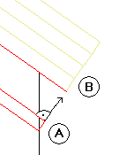
Depending on the shape you selected for the eaves and the ridge, the parameters you need to define are displayed graphically.
When you click ![]() beside Height of TL above roof, you can specify whether the height value is to be based on the top or bottom of the component. This way, when creating a series of rafters below a roof covering, for example, you can specify that the top level of the rafter placement is based on the bottom level of the roof covering.
beside Height of TL above roof, you can specify whether the height value is to be based on the top or bottom of the component. This way, when creating a series of rafters below a roof covering, for example, you can specify that the top level of the rafter placement is based on the bottom level of the roof covering.
Example
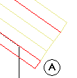
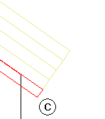
When you change the Height of TL above roof value for an entire series of rafters, the program will move the rafters perpendicularly to the roof pitch, ensuring a smooth transition between the rafters and the roof covering. The position of the rafters in plan will update automatically.
Example
Roof Pitch and Eave Height Reference Plane are locked during entry; the values they display merely reflect the settings of the roof plane or of the temporary custom reference plane.
When modifying steel and timber elements, you can enter new values for the Roof Pitch and Eave Height Reference Plane parameters and thus alter the pitch later. This is useful if, after modifying the roof, you want to update the rafters so that they match the changes in the roof, for example.
As the Roof pitch and Opposite pitch parameters and the Height of rafter and Height of opposite rafter values are mutually dependent, the ridge may be inclined:
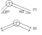
Height of opposite rafter:
(1) Inclined ridge when pitches are different
(2) Inclined ridge when rafters differ in height
Placing parameters (for rafter-supporting purlins)
This is where you can enter an overhang at the start and end of the rafter-supporting purlin (relative to the direction in which it is entered).
The Height of TL above roof value and the Roof pitch and Eaves height of reference plane parameters work in the same way as for rafters.
Placing parameters (for posts)
You can use the Placing angle parameter to specify the angle at which the post is created in plan.
Shape (for steel, timber elements)
![]()
![]()
This is where you can determine the shape of timber elements.
Advanced attributes (for steel, timber elements)
Insertion depth (for beams)
This is where you can define the depth by which the beam cuts through the rafter.
Surface elements in sections
These attributes control how rafters are displayed in sections and in animation:
![]()
![]()
While defining parameters, you can save the settings as a favorite file or retrieve favorite files you have already saved.
| (C) Allplan GmbH | Privacy policy |

 -->
--> 
 -->
--> 
