![]() Configuration Double wall: calculation
Configuration Double wall: calculation
Lattice girder parameters for double walls.
![]() 'Parameters' tab
'Parameters' tab
![]() The The girder shell is the ... leaf parameter was discarded a long time ago. Now the lattice girders are always associated with the invisible leaf; in other words, the invisible leaf is always leaf 1 (which is produced first).
The The girder shell is the ... leaf parameter was discarded a long time ago. Now the lattice girders are always associated with the invisible leaf; in other words, the invisible leaf is always leaf 1 (which is produced first).
If this parameter was not set to The girder shell is the invisible leaf in earlier versions, drawing files with double walls designed in this manner must not be edited in Allplan 2008 or later. It is essential that you create all production data in the version that was used to design the relevant double walls. Otherwise, reinforcement calculations might yield incorrect results!
Consider lattice girders:
If this check box is selected, then in the calculation of a reinforcement type in accordance with 'as-req.', the bottom or top boom is taken into account.
Minimum girder length:
Shorter girders are omitted.
Round length to:
The rounding value for the girder length.
Rounding:
Don't: no rounding.
Exact: 1-4 = rounded down, 5-9 = rounded up
Round down: lengths are rounded down to the above value.
Round up: lengths are rounded up to the above value.
Height of anchorage bars [%]:
This setting determines the length of the girder anchorage bars. The value relates to a percentage of the girder length up to which the bars are to be installed.
Enter 0 to disable the function.
Width of anchorage bars:
Width of the anchorage bars. Longitudinal bars in this region are moved.
Spacing between anchorage bars:
Spacing between the individual anchorage bars (see above)
![]() 'Height option' tab
'Height option' tab
Calculate girders based on:
Option 1: the girder height is calculated from the wall thickness minus the concrete covers and from twice the value of the bar thickness entered. In addition, the tolerances specified are taken into account.
This option allows you to influence calculations as the girder heights are often specified differently in the girder catalog (i.e. the height between the bottom and top boom is not given).
Option 2: the girder height is calculated from the wall thickness minus the concrete covers and the actual diameters of the first cross bars. If the cross bars are not in layer 1, all the diameters of the outer bars are also included. In addition, the tolerances specified are taken into account.
Option 3: the girder height is calculated from the wall thickness minus the value specified. The program adjusts the concrete cover so that the combination of possible spacers and calculated cross bars is as close as possible to the value specified. It is essential that the entire reinforcement is defined before it is created. Otherwise, the concrete cover cannot be calculated correctly. The tolerances specified are taken into account.
![]() 'Limits for height option' tab
'Limits for height option' tab
Round required girder height to cm:
The required lattice girder height is calculated from the wall thickness and other parameters (depending on the selected option). The result of this calculation can be rounded:
Do not round: no rounding.
Round exactly: 1-4 = rounded down, 5-9 = rounded up
Round up: the girder height is rounded up [cm].
Round down: the girder height is rounded down [cm].
Note:
In practice this setting only has any meaning if your girder catalog has very small increments, i.e., if the wall thicknesses that can be produced differ by very little (1-2 cm). In general girders are only installed that do not exceed the calculated height.
Tolerances for girder height calculation:
Limits taken into account when lattice girders are calculated automatically using options 2 and 3. If these limits cannot be met, the program will issue a message and the lattice girder will not be installed. In this case, the wall element is marked in accordance with the marking option specified.
![]() 'Distribution' tab
'Distribution' tab
Criterion for placing girders:
Criteria for distributing girders for fitted panels:
Two at least: there are to be at least two girders even for the smallest panels.
Edge offset maintained: the edge offset is always maintained. That means for the smallest panels only one girder is used.
Minimum girder spacing:
Minimum offset between the girders that under no circumstances must be reduced.
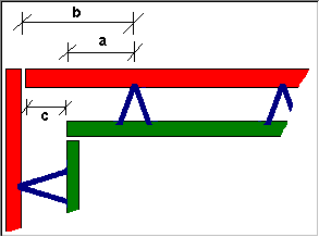
Edge distance for shorter leaf:
The limit value for the minimum distance to the panel edge (see diagram, A) of the shorter leaf.
The program attempts to use the edge distance defined by the reinforcement type (which is measured from the longer leaf). Whether this or the previous parameter has priority depends on which has the larger distance to the shorter leaf. In order to ensure that there is sufficient space for any corner reinforcement, this set minimum spacing is not to be reduced.
Edge distance for longer leaf:
The limit value for the minimum distance to the panel edge (see diagram, B) of the longer leaf.
The program attempts to use the edge distance defined by the reinforcement type (which is measured from the longer leaf). Whether this or the previous parameter has priority depends on which has the larger distance to the shorter leaf. In order to ensure that there is sufficient space for any corner reinforcement, this set minimum spacing is not to be reduced.
Max. difference between offsets:
Maximum distance of the longer leaf to the shorter leaf (see diagram, C). If this value is exceeded and Option 2 is not enabled in the Edge offset option tab, the program will take the girder's edge distance from the reinforcement type catalog or reinforcement parameters.
![]() 'Edge offset option' tab
'Edge offset option' tab
Calculate offset to girder edge based on:
Option 1: the program opts for the girder edge offsets entered in the Distribution tab.
The edge offsets are ignored when
Option 2: the girder edge offsets on the Distribution tab are always used (even when the distance between the longer leaf and the shorter leaf is greater than the offset to girder edge and/or the value specified for C on the Distribution tab).
| (C) Allplan GmbH | Privacy policy |
