![]() 'General' tab
'General' tab
Max. number of data blocks:
You can set a maximum for the number of data blocks. If a pallet exceeds this number, then the rest of the data is discarded. It is necessary to do this as otherwise the plotter may crash if it has to handle too much data.
Note:
Every line that is printed corresponds to a data block. Thus, it makes sense e.g. to print only up to a certain length of shell marker in order that the amount of data transmitted for complicated fitted panels does not become too large.
Plotter type:
Plotter, MRP, FormwRob, PV+BV, ARIA, MRP+FormwRob, Laser
The plotter type has an effect on the data created (depending on the driver used):
Plotter: plotter data without cross shutters.
MRP: combined device that prints, sets the cross shutters and cleans. The program creates plotter data commands to set up the cross shutters.
Formwork robot: the program creates plotter data commands to set up the formwork.
PV+BV: PUMAT - plotter and concrete spreader.
ARIA: ARIA large plotter.
Laser: for laser projection works. In addition, header data are created.
Sorting:
If yes, the plotter data are sorted in order of coordinates and transferred. If no, then data are sent in the current order.
Line overlap check:
The plotter data are checked for lines obscuring other lines; any superfluous lines are omitted. The following parameters set the ranking of the lines in this respect.
Priority line types:
Enter a ranking number for the line overlap check.
Positive value: the higher value line types have the highest priority.
Negative value: the higher value line types have the lowest priority.
Priority line colors:
(see NC generator – color numbers or color assignment)
Enter a ranking number for the line overlap check.
Positive value: the higher value line colors have the highest priority.
Negative value: the higher value line colors have the lowest priority.
Transfer section type for fwk robot:
For AIA-CAD V7.31 and higher only
![]() 'Formwork marker' tab
'Formwork marker' tab
Panel edges with no bar overlap:
solid, stroke, dash-dot, dotted lines
This sets the line type for panel edges with no bar overlap.
Shell side marked from [m]:
You can set here from where the longitudinal panel edge is marked if it has no bar overlap.
Panel edges with bar overlap:
solid, stroke, dash-dot, dotted lines
This sets the line type for panel edges with bar overlap.
Shell side marked from [m]:
You can set from where the longitudinal panel edge is marked if it has a bar overlap.
Recess edge in panel:
solid, stroke, dash-dot, dotted lines, automatic
You can set the line type for recess edges in the panel.
AUTOMATIC: partial recess (niche) BOTTOM = stroke line. Partial recess (niche) TOP = solid line
Shell side marked from [m]:
You can set here from where the longitudinal panel edge is marked.
Shell marking length (0=none) [m]:
You can specify the length of the formwork marker. (A short dash at 90° to the panel edge)
Show girder marking:
none, leaf1, leaf 2, leaves1+2
Parameters for wall panel production: the position of the girder is marked in leaf II in order to avoid interfering with fixtures.
Girder marking length (0=none) [m]:
Length of girder marker (see above). 0 = none
Girder marker offset [m]:
You can set the offset for the girder marker.
If the value is 0, then only 1 dash per girder end (placed centrally) is printed. If not 0, then 2 dashes are printed at the set offset.
Stop marking length (0=none) [m]:
If production is carried out on a wider pallet than standard (e.g. slab panels on a pallet for walls), then 3 dashes are placed along the length to be used (start, middle, end) to mark the stop runner. If the value entered here is 0, then the function is disabled and the panel edges are shown with a formwork marker.
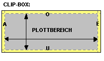
![]() 'Clip box' tab
'Clip box' tab
Clipping:
The area around the edges of the pallet can be clipped by the plotter to avoid interference e.g. with fixed cross shuttering. The width of this area can be set as follows:
Offset
to start of pallet S
to end of pallet E
to bottom of pallet B
to top of pallet T
![]() 'Labeling' tab
'Labeling' tab
Include panel numbers:
You can set whether or not the panel numbers are printed on the pallet. The size of the numbers is determined by the symbol size programmed into the plotter.
Include pallet number:
You can set whether or not the pallet numbers are printed on the pallet. The size of the numbers is determined by the symbol size programmed into the plotter.
Change y position of the pallet number:
To ensure that the pallet number does not always appear in the same place, the y position can be changed using a random number generator.
Only mark every second number:
Every second pallet number is printed.
Symbol width, symbol height
A plotter has internal symbols available (for the pallet numbers and decimal points and fixtures). CAD symbols are transferred with a code number and the symbol reference point (driver dependent). To ensure that the reference point is correctly transferred you have to enter the information here to pass the symbol size to the NC generator.
Symbol offset:
The plotter writes the symbols for the pallet number using a fixed offset. To ensure that the reference point is correctly transferred you have to enter the information here to pass the symbol size to the NC generator.
Line length for point symbol:
Point symbols are displayed as lines. This makes them easier to see. This is where you define the line length.
Max. y value for symbol overlap:
If a symbol overlaps the edge of the panel, the NC generator discards it so that a break in production is avoided. (For example an electrical socket at the edge of a panel.) Here you can set how much a symbol can overlap the panel edge without bringing production to a halt.
Symbol transfer:
decimal, ASCII code
The transfer of a plotter symbol, e.g. an electrical fixture, is done using a numerical code (driver dependent). Here you can specify whether the number is transferred as a decimal number or an ASCII code. Default setting = decimal.
See also fixture catalog.
Split up symbols into lines:
Symbols can also be transferred as single lines. In this case the symbol size entered above will be used, i.e. you can alter it. Another advantage is that symbols that are in the panel edge area are clipped, i.e. partially printed.
The disadvantage arising from this is the larger numbers of data blocks (particularly for cruciform symbols and numbers of pallets or panels), which can lead to memory overruns in a lot of machines.
![]() 'HP plotter' tab
'HP plotter' tab
Create header data:
The program creates header data (project data) before creating geometric information.
Line feed after each command:
A line feed control character (CRLF) is inserted after each command.
![]() 'Fixtures' tab
'Fixtures' tab
Line type for linear fixtures and surface form fixtures:
As per fixture catalog, automatic
You can set the line type for linear fixtures and surface form fixtures thus:
As per fixture catalog: the assignment of plotter lines in the fixture catalog applies.
Automatic: fixture BOTTOM = stroke line. Fixture TOP = solid line. If the display setting in the fixture catalog is none, then the fixture is NOT printed, whatever the setting made here.
Transfer upstands:
The shapes of concrete wall upstands cannot be transferred to the plotter if the plotter type (see above) is not set to "Formwork robot".
Line types for upstands:
solid, stroke, dash-dot, dotted lines, automatic
This sets the line type for panel edges with bar overlap.
Automatic: upstand BOTTOM = stroke line. Upstand TOP = solid line.
![]() 'Color plotter' tab
'Color plotter' tab
The color controller software is not supplied with the program as standard and can be obtained as an extra.
Multi-color plotting:
The color control feature can be enabled or disabled. At the moment this is only possible using the NCGASC30 driver.
Max. number of colors:
Limit for the number of colors that can be processed by the plotter. Any higher color numbers are automatically converted into standard colors.
Color numbers for:
Panel edges with no bar overlap
Panel edges with bar overlap
Recess edge in panel
Partial recess top
Partial recess bottom
Upstand top
Upstand bottom
Assign the color numbers as you require.
![]() 'Color assignment' tab
'Color assignment' tab
For fixtures (MRP device):
The CAD color (see fixture definition) can be assigned to a plotter color.
Attention: Only standard colors (1-16) can be used otherwise the color is interpreted as color number 1.
| (C) Allplan GmbH | Privacy policy |

