![]() 'Mirror elements' tab
'Mirror elements' tab
Mirror coordinates, leaves I / II:
no, x, y, x + y
For leaves I and II of double walls, you can mirror the coordinates of the element. This also defines the origin from which the coordinates are measured.
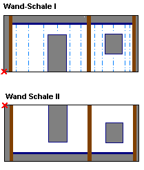
Mirror coordinates of slabs / solid walls:
like wall leaf I, no, x, y, x + y
Here you can mirror the coordinates for slab elements and solid walls in the same way as for leaf I of double walls or independently of this setting. This defines the origin.
Round coordinates:
Define whether the coordinates are to be rounded off. Coordinate are always rounded up/down to the exact value [mm].
![]() 'Mirror data' tab
'Mirror data' tab
Mirror X/Y coordinates of individual data blocks:
Plotter:
Cross shutters:
Longitudinal shutters:
Oiler:
Cross bars:
Longitudinal bars:
Girders:
Fixtures:
Concrete spreader:
Meshes and stirrup meshes:
no, x, y, x + y
The coordinate entries can be mirrored. This allows the origin to be changed for individual machines or the data rotated.
![]() 'Reference points of bars and girders' tab
'Reference points of bars and girders' tab
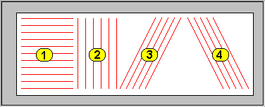
The reinforcement elements are transferred with only their start points, insertion angles and lengths. It is therefore important to specify their reference points (= bar intersection point):
Location of reference points
Scenario 1: left, right
Scenario 2: bottom, top
Scenario 3: bottom left, top right
Scenario 4: bottom right, top left
Changing bending shapes:
No, cross bars, longitudinal bars, cross+long
If a bending shape is only at the end of a bar then the bar in question can be turned.
Location of reference points for shear girders:
Near panel edge: the insertion angle is 0 or 180 degrees depending on the orientation of the shear girders (the transferred reference point is accordingly left or right). Attention: This function cannot be used on all machines.
As above: insertion angle and reference point are determined in as in scenarios 1-4.
| (C) Allplan GmbH | Privacy policy |
