![]() Tool(s): Design, Connections
Tool(s): Design, Connections
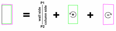
Symbols used to model connections between walls and columns have to be structured as follows:
1. Contact line:
The symbol has to include just one 2D line which is drawn with color = 1 (black). This line represents the contact line between the wall and the column and its length and the length of the actual contact line between the wall and the column have to be exactly the same. The orientation of this line (i.e. the position of points P1 and P2) is important because it defines the symbol's position relative to the wall/column (see sketch!).
2. Polygon for wall:
The symbol has to include at least one closed 2D polyline which is drawn with color = 4 (green). This polyline is used to create a fixture which helps you model the wall. The geometry has to match the plan view of the object to be modeled. The orientation of this polyline is important. When you enter a polyline in the mathematically positive/negative direction, its volume is added/subtracted.
3. Polygon for column:
The symbol has to include at least one closed 2D polyline which is drawn with color = 5 (magenta). This polyline is used to create a fixture which helps you model the column. The geometry has to match the plan view of the object to be modeled. The orientation of this polyline is important. When you enter a polyline in the mathematically positive/negative direction, its volume is added/subtracted.
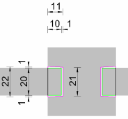
Example:
| (C) Allplan GmbH | Privacy policy |
