![]() Register 'View - parallel projection' / 'View - isometric view' / 'Section' tabs
Register 'View - parallel projection' / 'View - isometric view' / 'Section' tabs
To help you define the direction in which the precast element is viewed, the program displays the selected element type as a rectangular slab panel, wall or box (structural precast element) in the graphics area above the parameters. Depending on the selected element type, you can make different settings for the Principal directions. The actual viewing direction and rotation of the view as well as the required isometric setting are defined in the Projection area.
General
Name:
Any name that is displayed in the tree structure of the layout catalog.
Principal directions
Direction definition A:
Used for slab elements to define direction 6:
You cannot change this setting for wall elements and structural precast elements. For these elements, direction 1 is always the visible wall surface or the viewing direction defined for a structural precast element.
Direction definition B:
Specify the direction which is used for the orientation of the element in the element plan:
Projection
Viewing direction:
Specify the side from which the element is viewed and thus displayed in the view or section. You can also define the viewing direction by clicking in the isometric representation of the element in the graphics area. You can do this without having to select the Viewing direction line.
If a view or section is associated with another view or section by an anchor and the Align component option is selected, the viewing directions presented for selection are reduced to appropriate ones.
In conjunction with isomeric views, the viewing direction you specify here is simply used as an initial selection.
Rotation:
You can define the positions of the individual edges. The Rotation line shows the edge on the right side. You can also define the direction in the graphics area by clicking ![]() and
and ![]() . You can do this without having to select the Rotation line.
. You can do this without having to select the Rotation line.
When a view or section is associated with another view or section by an anchor and the Align component option is enabled, a rotation is not possible.
Isometric:
This parameter is only available on the View - isometric view tab. You can specify the actual direction of the isometric view. Depending on the Viewing direction specified, the isometric views presented for selection are reduced to appropriate ones. You can also define the isometric view by clicking it in the graphics area at the top. You can do this without having to select the Isometric line.
The viewing directions 7 – 10 from the top and 11 – 14 from the bottom are defined in relation to the viewing directions 1 – 6 as follows:
For slabs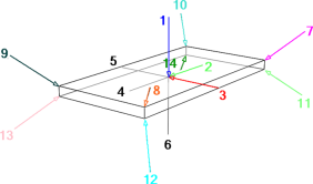
For walls and structural precast elements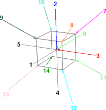
Section
This area is only available on the Section tab.
Section start / Section depth:
You can define the Section start and Section depth as a percentage of the component depth. The position of the section depends on the viewing direction.
Example: You want to display a section in the area of a column footing. The viewing direction is from the top. For example, you can enter 85% for the section start and 10% for the section depth. When the component is viewed from the bottom, you can enter 5% for the section start and 10% for the section depth, for example. The area displayed is the same, regardless of which setting you choose.
X factor / Y factor:
You can specify a zoom factor in the x and/or y direction. This way, you can display sections at a scale that differs from that used for views.
Section identifier
This area is only available on the Section tab.
Name:
Any name of the section that is added to the section symbol and used for the section identifier generated automatically (section ... - ...).
Text attributes:
Enter or select attributes for the section identifier. The height and width of the text are entered in [mm] and the font angle in [degrees].
Section object
This area is only available on the Section tab.
Auto-update:
When you select this option, the section object updates automatically to reflect any changes you make to the geometry of the precast element. However, the program does not check whether the enlarged sections overlap other layout elements.
Using this option, you do not need to go through the time-consuming process of creating a completely new element plan after a few minor changes. In addition, you can get around an error-prone, manual adjustment of the section objects as this is done automatically by the program.
![]() 'Formwork/display' tab
'Formwork/display' tab
General
Formwork:
You can specify whether the Entire component or Individual layers of the component are displayed for multi-tier walls (double wall, wall panels, thermal wall).
Display:
You can choose to display the view or section as a wireframe model (Wire) or hidden line image (Hidden).
Stirrup shapes:
This setting is only available in front elevation (slabs) or plan view/soffit (walls).
You can specify whether the placement is always displayed in the view or section or whether it is only displayed when the stirrup shape is not distorted.
In the latter case, the stirrup shape must not be sloping in relation to the views or sections. Otherwise, it is not displayed in any view or section.
Show fixtures:
Whether fixtures are displayed or not depends on the setting specified on the Element plan tab of the fixture catalog. Here you can define how fixtures are displayed in accordance with the dimension line index.
All: the dimension line index of the fixtures has no effect on the scope of fixtures displayed.
These only: only the fixtures with the dimension line indices set are displayed.
These excluded: all fixtures are displayed except those with the dimension line indices set.
Dimension line index:
Use ![]() and
and ![]() to specify the entry to be used. The dimension line index assigned is displayed in the Index line.
to specify the entry to be used. The dimension line index assigned is displayed in the Index line.
Click ![]() to
to ![]() add new indices to or to
add new indices to or to ![]() remove existing indices from the Dimension line index dialog box.
remove existing indices from the Dimension line index dialog box.
Display
Layer
This setting is only available when you have selected Individual layers for the formwork in the General area. Use ![]() and
and ![]() to specify the relevant layer or click
to specify the relevant layer or click ![]() to open the table where you can define the display parameters for layers 1 to 6. Select the Display option to display the lines for selecting the reinforcement and fixtures to be displayed on the visible and invisible sides.
to open the table where you can define the display parameters for layers 1 to 6. Select the Display option to display the lines for selecting the reinforcement and fixtures to be displayed on the visible and invisible sides.
Display:
This setting is only available when you have selected Individual layers for the formwork in the General area. Specify whether the selected layer is displayed in the view or section. Select this option to display the lines for selecting the reinforcement and fixtures to be displayed on the visible and invisible sides.
Reinforcement visible / invisible side
Specify whether the reinforcement is displayed on the visible side and/or invisible side of the component or of the selected layer.
Fixtures visible / invisible side
Whether fixtures are displayed or not depends on the setting specified on the Element plan tab of the fixture catalog. You can define the scope of fixtures displayed in accordance with the dimension line index in the General area. Specify whether the fixtures are displayed on the visible side and/or invisible side of the component or of the selected layer.
Surface elements
Surface elements:
You can specify how surfaces are displayed.
No surface elements: surface elements are not displayed in hidden line images.
Fills only: fills are applied to the surfaces displayed in hidden line images. The fill color is derived from the element color or, if a surface is assigned, from the surface color of the precast element. Any textures are ignored.
Bitmap areas and fills: surfaces with textures are displayed as bitmaps in hidden line images. Fills are applied to surfaces without textures (the fill color is derived from the element color or surface color).
Note: Bitmap areas are only resized (cropped) correctly in parallel projections (elevation and isometric views). To produce realistic results in perspective views, you are advised to use granular surfaces such as sand, plaster or so on.
Transparency:
When you select this option, surfaces to which you have assigned a transparent surface appear transparent so that hidden surfaces become visible.
Adjacent edges
Remove adjacent edges:
When you select this option, the program merges surfaces up to the angle you specify in order to make curves appear smoother in hidden line images. Setting a larger angle causes curves to appear as a silhouette.
|
|
|
|
|
Off |
Angle |
Angle |
Visible edges
Lock attributes / Attributes:
When you select the Lock attributes check box, visible edges are created with the attributes set here. Otherwise, the format properties of the precast element are used.
Hidden edges
Display / Attributes:
When you select the Display check box, hidden edges are created with the attributes set here. Otherwise, the program does not create any hidden edges.
Boundary line
This area is only available for sections.
Display:
When you select the Display check box, boundary lines are applied to intersected component edges.
Overlap / Attributes:
You can define the value by which the boundary lines overlap in the unit of length set. In addition, you can specify attributes for the display of these lines.
Thick border
This area is only available for sections.
Display / Attributes:
When you select the Display check box, intersected edges are created with the attributes set here. Otherwise, the format properties of the precast element are used.
![]() 'Clipping path' tab
'Clipping path' tab
This tab is not available for isometric views.
Clipping path
Display:
When you select the Display option, the clipping paths of the sections generated automatically are displayed in this view or section.
Clipping line
Continuous / Length of line segments:
When you select the Continuous check box, the clipping line is drawn as a continuous line. Otherwise, the program creates line segments of the length specified that are attached to the min-max-box of the direction symbol. The unit of length is [mm].
Attributes:
Here you define the attributes that are used to display the clipping line.
Direction symbol
Place / Direction symbol:
When you select the Place check box, the clipping line is displayed with the selected direction symbol.
Symbol size:
This is where you define the size of the direction symbol. If you enter 0, the size of the direction symbol is determined automatically.
The direction symbol is created within a min-max-box whose height is equivalent to the predefined size and whose width is 1.6 times this height. If you enter 0 for the size, the text height of the label is used for the height of the min-max-box.
The height of the actual symbol is three-quarters of the height of the min-max-box. The offset between the tip of the symbol and the inner edge of the min-max-box is the same as the height.
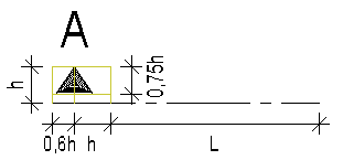
L = Length of line segments
Note: The line segments of the length specified are created after the min-max-box of the direction symbol.
Label
Text attributes:
Enter or select attributes for the section identifier applied to the section symbol. The height and width of the text are entered in [mm] and the font angle in [degrees].
You can specify the name of the relevant section in the Section identifier area of the Section tab.
![]() 'Text' tab
'Text' tab
This tab is only available for views in parallel projection. Except for the Hollow blocks area for slabs and the Mark number of reinforcement / fixtures areas for structural precast elements, the individual areas of this tab are only available when the viewing direction (View - parallel projection tab) is defined so that it is in the direction or in the opposite direction of Direction definition A.
Note: The height and width of the text are entered in [mm] and the font angle in [degrees].
Element number
Label / Text attributes:
Use this to specify the position and attributes of the label.
No: no element number is output.
Bottom left as placed: the element number is place in the corner at bottom left. In the slab program, this definition is based on the position in the placing drawing and in the wall program on the visible side of the elements.
Note: As slab panels are rotated in element plans, the number is usually at bottom left. However, the panels are always placed correctly as they are identified by the positions of their element numbers.
Centrally in the panel: the element number is placed in the middle of the element.
Smart architectural symbols
This area is only available when you have selected a slab or wall as the element type for the element plan.
Label / Text attributes:
Use this to specify whether and how smart architectural symbols are to be labeled and define the attributes for the label.
Mark number of reinforcement / fixtures
Label / Text attributes:
Specify whether mark numbers are assigned to the reinforcement or fixtures and define the attributes that are used for the labels. The mark numbers are created automatically, regardless of whether the element plan table is used or not.
Edge attributes
This area is only available when you have selected a slab or wall as the element type for the element plan.
Bar overlap / Length of inclined edges / Minimum length of edge:
Define whether all edges are to be labeled with the bar overlap and/or the length is to be included in labels for inclined edges. Enter the minimum length in [m] above which inclined edges are labeled.
Unit / Text attributes:
Specify which unit and attributes are to be used for labeling.
Bars between lattice girders
This area is only available when you have selected a slab as the element type for the element plan.
Label / Text attributes:
As an alternative to the longitudinal bars you can output the number of the bars that are between two lattice girders. The attributes defined for production are used.
Example: 4xd12 means that there are 4 bars of diameter Ø 12 between these girders. If there are no lattice girders, the entire longitudinal reinforcement is shown.
Miters
This area is only available when you have selected the double wall as the element type for the element plan.
Label / Text attributes:
Use this to specify whether miters at double walls are labeled and specify the attributes for the label.
Hollow blocks
This area is only available when you have selected the hollow core element or prestressed hollow core element as the element type for the element plan. In addition, it is only available for front elevations of the slab in the direction of span (viewing direction 2 or 4).
Numbering / Text attributes:
Specify whether the hollow blocks of hollow core elements and prestressed hollow core elements are numbered and specify the attributes for the label.
![]() 'Symbols' tab
'Symbols' tab
This tab is only available for views in parallel projection.
Symbols in drawing
Smooth edge / Bending shape:
Specify whether the symbol for smooth edges and the bending shapes of the supports are to be displayed.
Formwork symbol, File no. / Entry no.:
This setting is only available in front elevation (slabs) or plan view/soffit (walls).
Select the file and the entry of the symbol created at a scale of 1:1 in Allplan and saved in the Office path. The formwork bottom is marked with this symbol.
Symbols for formwork attributes
Symbols / Minimum length of edge / Offset to edge:
This setting is only available in plan view/soffit (slabs) or in front elevation (walls).
Specify whether you want to use symbols to display edges with formwork attributes and specify how long an edge must be so that a symbol is displayed and the offset between the symbol and the edge.
You can define the symbols for the different formwork attributes using Symbols for formwork attributes in the General - symbols area at top left.
Center of gravity in drawing
Center of gravity / Layer ... / Construction lines:
Specify whether the center of gravity of the Entire component or the centers of gravity of the Individual layers are displayed. If you do not want to display a center of gravity, select No. When set to Individual layers, you can select the individual layers. In addition, you can specify whether the center(s) of gravity are drawn as Construction lines.
Pattern line for bar overlap / special formwork
Display / Pattern no.:
When you select the Display check box, the pattern line selected in Allplan is applied to element edges with bar overlap or special formwork.
Position / Attributes:
Specify whether the pattern line is to be placed inside the element, centrally on the formwork edge or outside the element and enter the Height and Width of the pattern line in [mm]. If the value for the height and/or width is 0, the program uses a default value of 3 mm.
![]() 'Dim. lines' tab
'Dim. lines' tab
This tab is only available for views of all element types in parallel projection and for sections of structural precast elements.
You can specify settings for the dimension line and dimension text, which are usually defined while creating dimensions in Allplan.
Horizontal / Vertical dim. lines
Dimensioning / Mode:
You can specify whether you want to create normal dimensioning (relative) or dimensioning with cumulative values (absolute). When set to absolute, you can specify the direction in which the dimensions are added. You can also configure the program to add up values by working from the two sides towards the middle (on both sides).
Distance between view and dimension line:
[mm] Actual offset from dimension lines to elements when plotting, regardless of the selected reference scale.
Distance between dimension lines:
[mm] Actual offset between dimension lines when plotting, regardless of the selected reference scale.
Max. number of dim. lines at bottom/at top/on the left/on the right:
Specify the maximum number of dimension lines that are created automatically by the program.
Inclined dimension lines at outer edges
Create:
When you select the Create check box, the program creates inclined dimension lines at the outer edges (in addition to the horizontal and vertical dimension lines). The settings are the same as for horizontal and vertical dimension lines.
Dimension line parameters
Dim. line attributes:
Select attributes.
Text attributes of dim. line / of dim. group:
The dimension text height/width defines the real template size of dimension text.
For example, a number with a height value of 3.5 is always plotted out as 3.5 mm high, regardless of the selected reference scale.
Enter or select attributes. The height and width of the text are entered in [mm] and the font angle in [degrees]. The outermost dimension line with the total dimensions of the element is 1.3 times the text height.
Dimension group as additional text:
When this option is selected, identifiers for dimensioned elements are placed at the individual dimension lines. You can specify these identifiers in the General - dimension lines area at top left.
Arrowhead
Size of arrowhead for dim. lines:
You can set the size of arrowhead for the dimension lines here.
The size of the arrowhead changes associatively with the size of the dimension line delimiter.
![]()
A Dimension line
B 3 mm
Arrowhead for dim. lines, relative/absolute:
This is where you can select the arrowhead for normal dimensioning (relative) or dimensioning with cumulative values (absolute).
Size of symbol / symbol for elevation points:
You can set the size and type of the arrowhead used for elevation dimensioning of walls.
Advanced
Show dimension line:
You can choose to show or hide the dimension line here.
Dimension text
Dim. text unit:
You can set the unit of dimensioning here.
Round-off value:
The dimension figure computed by the system only appears rounded-off on-screen. Internal computations, however, continue to use the figure's original value.
Example:
Round-off value 5 0.1137m -> 0.115m
Round-off value 10 0.2384m -> 024m
Decimal places:
Enter the number of decimal places here.
Trailing zeros:
Enter the number of trailing zeros here. Enter the number of trailing zeros used to pad out empty decimal places.
Example:
The value 1.01 with:
4 decimal places, 4 trailing zeros will display as 1.0100
4 decimal places, 2 trailing zeros will display as 1.01
Dim. text position:
Position of the dimension text within the dimension line.
Dim. text offset:
You can set the actual offset between dimension text and dimension lines.
The offset is entered in mm; you can also enter negative values.
![]()
A Positive offset
B Negative offset
Exponent format:
You can toggle the exponent format on/off.
This option is only available when Dim. text unit is set to m, cm.
![]() 'Dimensioning' tab
'Dimensioning' tab
This tab is only available for views of all element types in parallel projection and for sections of structural precast elements.
The views and sections of structural precast elements are dimensioned based on the algorithm used for the automatic tools of the Shell module. Identical dimension lines are not drawn and the program automatically defines the position of the dimension line.
Layer depth
This area is only available when you have selected a slab or wall as the element type for the element plan.
Dimension:
Check box selected: for all fixtures that are not located on the exterior sides or in the middle of the wall or slab, a dimension line for the layer depth is created in plan view (wall) or front elevation (slab).
Requirement: the relevant element is enabled in the Dim. lines area.
Arcs
This area is only available when you have selected a slab or wall as the element type for the element plan.
Dimension:
As discrete lines: arc shaped panels forming part of a panel polygon must always be divided into discrete lengths. This setting dimensions the partial lengths on the dimension line.
As genuine arc: the program considers the polygonal shape as a circle and dimensions the center (with a radius arrow).
If the center of arc is beyond panel edge, then measure as discrete lines:
Check box selected: if the arc center is outside the element, then the arc segments are dimensioned (on the dimension line).
Check box not selected: the program always considers the polygonal shape as a circle and dimensions the center (with a radius arrow).
Allowable edge offset of center:
Limit value for the arc center outside the panel in order for the arcs still to be dimensioned.
Elevation specs
Basic edge / Panel edge / Recesses:
Select the check boxes of the elements you want to include in automatic elevation dimensioning. Only visible elements are dimensioned.
The top and bottom levels of Recesses are always dimensioned.
Dimension lines
Total dimension / Panel edge / Recesses ...:
Select the check boxes of the elements you want to include in automatic dimensioning using horizontal, vertical and inclined dimension lines. Only visible elements are dimensioned.
The following options are available for Overall dimensions: no dimension lines, horizontal dimension lines, vertical and horizontal dimension lines and vertical dimension lines.
Filling objects:
You can select a special dimensioning type for slab elements of the BubbleDeck design mode.
When you select the check box, all axes with balls are dimensioned. It is enough if the entire axis contains only one ball and all the other balls are hidden. If all the balls of an axis are hidden or if they have been removed due to a concrete strip or because they are too close to an edge or opening, the corresponding axis is not dimensioned!
Insulating boards / Facing layer / Concrete areas:
Dimensioning of insulating boards or tiles is based on the points on the element edges; dimensioning of insulation areas or areas for facing layers is based on the points on the edges of an area.
Note: Insulating boards and tiles are only dimensioned if they are placed at an angle of 0° or 90°.
Dimensions for center of gravity
Center of gravity / Layer ... / Dimension:
Specify whether the center of gravity of the Entire component or the centers of gravity of the Individual layers are dimensioned. If you do not want to dimension a center of gravity, select No. When set to Individual layers, you can select the individual layers. In addition, you can specify whether the center(s) of gravity are dimensioned horizontally, vertically or horizontally+vertically.
Other settings
Layer depth of fixture:
Specify whether the layer depth of fixtures that are not located on the exterior sides or in the middle of the wall or slab is to be dimensioned.
Panel edge, recesses:
Specify whether openings are to be dimensioned using common dimension lines (Dimension together) or whether a separate dimension line is to be created for each opening (Dimension separately).
| (C) Allplan GmbH | Privacy policy |


