![]()
![]()
|
|
|
Whenever you select a tool that uses polyline entry tools (e.g. pattern, hatching, room), the Input Options appear. You can use these options to specify how the polyline entry tools behave when you generate polylines based on existing elements and how architectural lines are to be handled.
Entering areas
![]() Single
Single
Use this to create single, discrete areas.
![]() Multi
Multi
Use this to create areas composed of several polygons. Hatching, patterns or fills are given the same group number; rooms are handled as a single entity. This way, you can make a series of separate rooms which the system will treat as a single unit in subsequent evaluations and analyses of the information in the building model.
![]() Plus,
Plus, ![]() Minus
Minus
If you selected ![]() Multi, you can use
Multi, you can use ![]() Plus and
Plus and ![]() Minus in the input options to specify whether each new polygon is to be added to or subtracted from the overall area.
Minus in the input options to specify whether each new polygon is to be added to or subtracted from the overall area.
Polygonizing existing elements
Polygonize elements on/off
When the check box is not selected, elements are ignored when you click them; only points are detected.
When the check box is selected, the elements you click are polygonized. You can use the options next to this check box to specify the type of polygonization.
![]() Polygonize entire element
Polygonize entire element
This uses the entire element that you clicked. The starting point defines the direction of polygonization. If the last point in the polyline coincides with the start or end point of the element, the direction does not need to be specified.
Use this option when the outline consists of entire elements.
![]() Define area of element to polygonize
Define area of element to polygonize
With this option, the program prompts you for the area with every element you click (from point, to point).
Use this option when the outline consists of segments.
![]() Enter reference point
Enter reference point
With this option, the program prompts you for the reference point with every element you click. This option uses a point on the element you clicked with a defined offset to the reference point. Click to define a new reference point and then enter the offset to the reference point. Use this option when you want to specify the outline based on existing elements (when you enter a dormer, for example).
![]() Area detection using additional point
Area detection using additional point
![]() Area detection using additional point combines areas bounded by lines and polylines to form a polygon. The inner or outer boundaries are used depending on whether the temporary point is inside or outside the outline.
Area detection using additional point combines areas bounded by lines and polylines to form a polygon. The inner or outer boundaries are used depending on whether the temporary point is inside or outside the outline.
By selecting ![]() Element filter, you can configure the program to ignore architectural lines when detecting areas.
Element filter, you can configure the program to ignore architectural lines when detecting areas.
![]() Area detection
Area detection
You can use ![]() Area detection to automatically detect the outlines of closed polygons. Closed areas delimited by design entities of any kind can be used as an outline polygon simply by clicking anywhere within the area. Allplan automatically detects and polygonizes the entire outline. The boundary elements can have points in common, they can intersect and they can touch. This automation feature can be turned on/off as required.
Area detection to automatically detect the outlines of closed polygons. Closed areas delimited by design entities of any kind can be used as an outline polygon simply by clicking anywhere within the area. Allplan automatically detects and polygonizes the entire outline. The boundary elements can have points in common, they can intersect and they can touch. This automation feature can be turned on/off as required.
Note: The Minimum distance between points setting in the ![]() Options on the Desktop environment page also applies to the
Options on the Desktop environment page also applies to the ![]() Area detection tool. To make sure that outlines with small gaps are detected, you can increase the minimum distance between points temporarily.
Area detection tool. To make sure that outlines with small gaps are detected, you can increase the minimum distance between points temporarily.
![]() Island detection,
Island detection, ![]() Inverse island detection
Inverse island detection
When ![]() Island detection is switched on, closed outlines within an area are detected and cut out automatically.
Island detection is switched on, closed outlines within an area are detected and cut out automatically.
When you select ![]() Inverse island detection, closed outlines are not cut out but filled out with the selected surface element. It is the area around the 'island' that remains empty.
Inverse island detection, closed outlines are not cut out but filled out with the selected surface element. It is the area around the 'island' that remains empty.
You can use these tools only in conjunction with ![]() Area detection using additional point and
Area detection using additional point and ![]() Area detection.
Area detection.
Number of segments / Rise
![]() Kreisteilung
Kreisteilung
Der Polygonisierungswert wird als Kreisteilung interpretiert. Über den Wert bei ![]() Kreisteilung legen Sie fest, mit welcher Aufteilung ein Kurvenelement dargestellt wird. Der Wert 120 bedeutet beispielsweise bei einem Kreis, dass der Vollkreis als Fläche dargestellt wird, die aus einem fiktiven 120-Eck entsteht. Je größer die Genauigkeit sein soll oder je größer der Radius ist, desto höher sollte die Kreisteilung sein. Zulässige Eingaben liegen zwischen 36 und 360.
Kreisteilung legen Sie fest, mit welcher Aufteilung ein Kurvenelement dargestellt wird. Der Wert 120 bedeutet beispielsweise bei einem Kreis, dass der Vollkreis als Fläche dargestellt wird, die aus einem fiktiven 120-Eck entsteht. Je größer die Genauigkeit sein soll oder je größer der Radius ist, desto höher sollte die Kreisteilung sein. Zulässige Eingaben liegen zwischen 36 und 360.
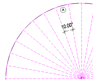
(A) Kreisteilung =36; das ergibt einen Winkel = 10°
![]() Rise
Rise
The polygonization value is interpreted as the rise. The value you enter for ![]() Rise defines the maximum rise of the secant relative to the arc (in mm). As a result, the curve is polygonized so that the maximum offset of the polyline's segment to the curve is less than or equal to the value your specified. This setting produces more accurate results than the number of segments.
Rise defines the maximum rise of the secant relative to the arc (in mm). As a result, the curve is polygonized so that the maximum offset of the polyline's segment to the curve is less than or equal to the value your specified. This setting produces more accurate results than the number of segments.
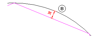
(B) Rise (38mm or less)
Element filter
![]() Element filter
Element filter
Ignore lines of architectural elements in plan
Ignore 2D surface elements (hatching, patterns, fills, bitmap areas, smart fit placements)
For example, when you work with area detection
When you select the ![]() Element filter, lines of architectural elements and 2D surface elements are ignored when you use
Element filter, lines of architectural elements and 2D surface elements are ignored when you use ![]() Area detection or
Area detection or ![]() Area detection using additional point. Use this option to automatically apply surface elements like hatching, patterns etc. to adjacent outlines that are separated by arcs, splines or curves.
Area detection using additional point. Use this option to automatically apply surface elements like hatching, patterns etc. to adjacent outlines that are separated by arcs, splines or curves.
Background information: curves are polygonized based on the number of segments specified.
When a second (third...) area is entered, Area detection may take a long time and/or produce incorrect results because Allplan detects both the outline of the surface (2D line) and the boundary line of the polyline of the first area.
Back, Help
![]() Back
Back
This undoes the last point you entered.
![]() Help for entering polylines
Help for entering polylines
This displays help for the polyline entry tools provided in the input options.
| (C) Allplan GmbH | Privacy policy |
