![]()
![]()
|
|
|
Creating a boundary line at the intersections of parametric lines or at parametric points via a consecutive sequence of points whose connection (polyline) describes the border of the cross-section.
Note: The boundary line must be closed by selecting the first point again to completely define the border of the cross-section.
There are two input methods that can be switched between at any time (even during the same input procedure) via the properties window (or by pressing TAB), namely point-by-point or line-by-line input. With point-to-point input the points of intersection on the parametric lines (or parametric. points if necessary) are selected directly. If more than two parametric lines run through a point, the desired point of intersection of the corresponding lines must be selected after clicking in the selection box that opens. With line-to-line input the points of intersection on the parametric lines are defined by selecting the corresponding parametric lines, i.e. selecting two lines in each case defines a point of intersection on the boundary line.
As a result, line-by-line input is useful, for example, if many parametric lines run through the same point and there is a need to define the desired point of intersection of the corresponding parametric lines, which are not selected retrospectively, but are selected at the start.
However, the use of line-by-line input is mandatory when using parametric lines in the arc category. At this point, the program must be informed that the boundary line should not run straight from one point of intersection to another, but along the circle line, which is done by selecting the circle line directly. The easiest way to do this is to revert back to point-by-point input. If a circle line is involved, the input sequence must be carried such that after switching to line-by-line input, the circle line itself is always entered first, then the corresponding parametric line (which may also be another circle line) is selected for the desired point of intersection to define the starting point of the boundary line along the circle line. This defines the starting point and course of the boundary line along the circle line and then, in the next step, the end point of the boundary line along the circle line can be defined again using the point-by-point input method (i.e. after switching to point-by-point input by directly selecting the point of intersection of the circle line and the corresponding parametric line). In the case of boundary lines along two (or more) consecutive intersecting circular lines, proceed in the same way with line-by-line input, switching to point-by-point input only at the end of the last circular line. (Note: If the line-by-line input is retained for the definition of the end point of the boundary line, the corresponding parametric line and then the circle line along which the boundary line was defined must be selected first). To illustrate the input sequence, see the two examples below for defining boundary lines along arcs.
To create a boundary line
Note: You can successively delete the last point defined by pressing the backspace key.
Note: Press ESC to cancel the entire input process and exit the function.
Note: You can also continue the definition of an unclosed boundary line at a later point in time. See Insert Boundary Line Point.
Examples for defining boundary lines along arcs
The following two images show the numbered click sequence with the corresponding input method selected (point-by-point or line-by-line).
Example 1: Boundary line along an arc
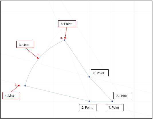
The point-by-point input method is used by default(steps 1 to 2). To define the starting point and the course of the boundary line along the circle line, switch to line-by-line input in the next step then first select the circle line (step 3) and then the parametric line (step 4) is selected, from the point of intersection of which the boundary line starts along the circle line. In the last step for defining the boundary line along the circle line, you switch back to point-by-point input and define the end point of the circle line by directly selecting the corresponding point of intersection (step 5). The boundary line can then be continued and completed as usual (steps 6 to 7).
Example 2: Boundary line along two consecutive, intersecting arcs
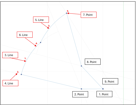
Steps 1 to 4 are carried out as stated above. The boundary line is then created along the second arc according to the same principle, i.e. (while retaining the line-by-line input), starting with the circle line of the second arc (step 5) and then the parametric line (the first circle line in this case) (step 6) is selected, at the point of intersection of which the boundary line should start along the second circle line. Finally, as above, the definition of the boundary line along the circle line is again completed with the point-by-point input by selecting the corresponding point of intersection (step 7). The remaining steps (steps 8 to 9) must then be continued as standard.
|
(C) ALLPLAN GmbH |
Privacy policy |
