![]()
![]()
|
|
|
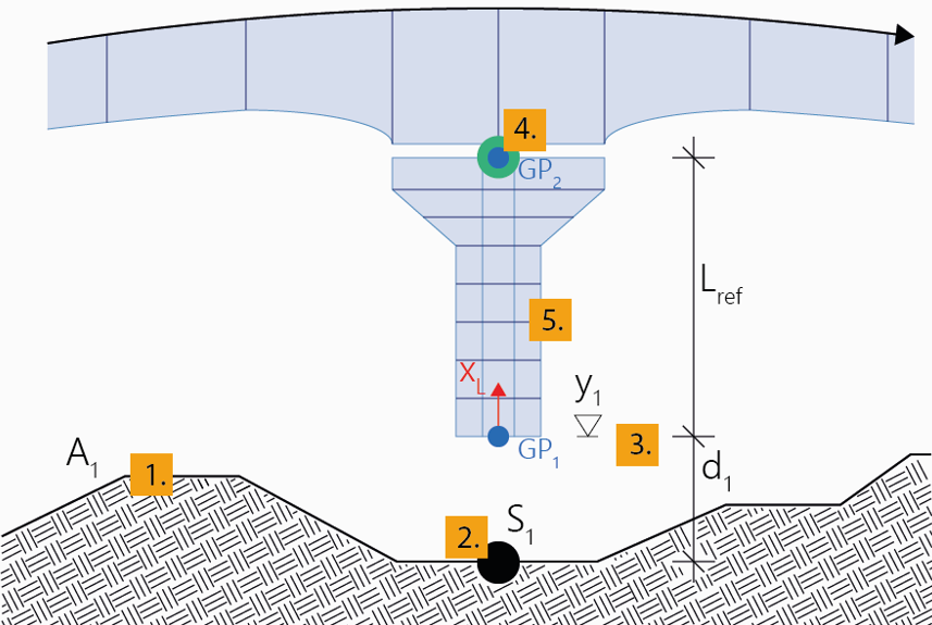
Interactively create a structural member of the type “pier” related to an axis and a reference point of a structural member of the type “girder”
Piers of this type of definition are positioned between a particular station of an axis in a certain vertical distance (offset) from it and a reference point of a structural member of the type “girder”. The first position defines the point of origin of the pier axis (Geometric Position 1), the second position (Geometric Position 2) the reference length.
The same explanations and notes apply as given in Pier relative to axis.
Note: The following input description relates to the station subdivision type Free. When using the options Equidistant and Begin & End, the steps 8 to 11 and 13 are omitted. When using one of these two options, you must select the cross section (step 7) already in arbitrary step before. See Piers for details regarding these options and further general explanations regarding the definition of piers.
To interactively create a pier relative to an axis and a reference point
A new pier will be created in the menu Piers in the project navigation tree.
Note: Select the type of the distance to be defined (relative to the selected position on the axis or as an absolute height through this point) during input in the menu Geometric Position 1 in the Property window.
Note: The reference point (GP 2) must lie above the point of origin (GP 1) to receive a positive reference length. (The input is immediately checked by the program and, as the case may be, not permitted).
Note: Select the Type of the start station in the menu Stationing in the Property window.
Note: Select the Type of the stations to be added in the menu Stationing in the Property window.
Note: In the course of the input procedure described above, you can anytime insert a subdivision point in an already existing pier segment by simply clicking on the desired position within the already created pier segment.
|
(C) ALLPLAN GmbH |
Privacy policy |
