![]()
![]()
|
|
|
Interactively create a structural member of the type “pier” directly related to an axis with additional possibilities of definition
Compared to the standard tool Pier at station point, this tool provides additional possibilities for defining a relative length and for subdividing stations.
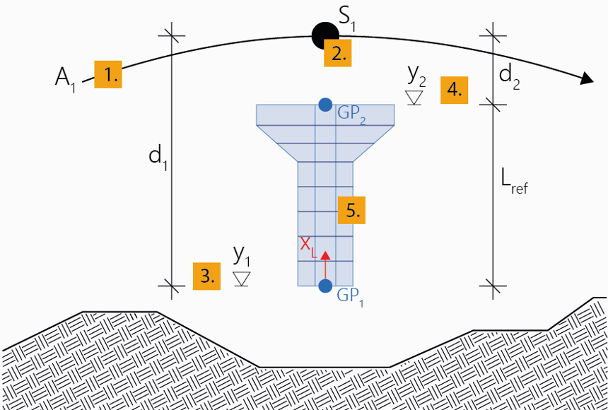
Piers of this type of definition can be directly positioned at a certain station of an axis in a certain vertical distance (offset) from it. This position defines the point of origin of the pier axis (Geometric Position 1).
In a further step, a second position is specified (Geometric Position 2) which is used for defining a reference length (reference length = distance from Geom. Pos. 1 to Geom. Pos. 2).
This reference length enables an additional type of definition for the subdivision of stations besides local and global, namely relative.
Within the interactive definition, the sequence of the definition of the positions needs to be observed: The Geometric Position 1 is always defined first, and afterwards, based on that, the Geometric Position 2 upwards in positive vertical direction (positive local x-direction (global Y)) which also determines the direction for the relative length. (The program checks that and does not allow a different interactive input).
The sequence of the definition of the stations (start/end station or top/bottom edge of the pier) does not matter.
Thus, the general workflow is to first define a reference length along the pier axis by means of the two Geometric Positions, and after that the pier is defined by the input of stations. This procedure corresponds to the station input Free and can be shortened/simplified using the options Equidistant or Begin & End (see the following note).
Note: The following input description relates to the station subdivision type Free which can be selected during input in the Property window. Alternatively, you can use the option Equidistant to directly subdivide the pier between the two defined Geometric Positions equidistantly (or also arbitrarily), i.e. the length of the pier equals the reference length - (in this case the steps 8 to 11 and 13 are omitted). Using a third option Begin & End (as a variant of the option Equidistant), you can define the same segment without subdivision, i.e. stations points only at begin and end. When using one of these two options, you must select the cross section (step 7) already in arbitrary step before.
See Piers for general explanations regarding the definition of piers.
To interactively create a pier relative to an axis
A new pier will be created in the menu Piers in the project navigation tree.
Note: Select the type of the distance to be defined (relative to the selected position on the axis or as an absolute height through this point) during input in the menu Geometric Position 1 in the Property window.
Note: Select the type of the distance to be defined during input in the menu Geometric Position 2 in the Property window (in addition to relative distance and absolute height there is the possibility of relative to origin).
Note: Select the Type of the start station in the menu Stationing in the Property window.
Note: Select the Type of the stations to be added in the menu Stationing in the Property window.
Note: In the course of the input procedure described above, you can anytime insert a subdivision point in an already existing pier segment by simply clicking on the desired position within the already created pier segment.
|
(C) ALLPLAN GmbH |
Privacy policy |
