Pier relative to two axes
Interactively create a structural member of the type “pier” related to two axes
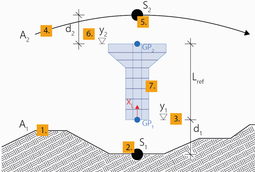
Piers of this type of definition are directly positioned between two particular stations of two axes, in each case in a certain vertical distance (offset) from them. The first position defines the point of origin of the pier axis (Geometric Position 1), the second position (Geometric Position 2) the reference length.
The same explanations and notes apply as given in Pier relative to axis.
Note: The following input description relates to the station subdivision type Free. When using the options Equidistant and Begin & End, the steps 10 to 13 and 15 are omitted. When using one of these two options, you must select the cross section (step 9) already in arbitrary step before. See Piers for details regarding these options and further general explanations regarding the definition of piers.
To interactively create a pier relative to two axes
- Click Pier relative to two axes.
- Optionally, edit the name and the description and confirm the input with OK.
A new pier will be created in the menu Piers in the project navigation tree.
- Click the first axis in the 3D View window to which the pier axis should be connected.
- Move the mouse along this axis in the View window to specify the desired station at which the pier axis should be connected, and confirm it with a mouse click.
- Move the mouse in vertical direction in the View window to specify the desired distance in vertical direction (local x-direction (global Y)) related to the previously selected position on the first axis to define the position of the point of origin of the pier axis (Geometric Position 1). Confirm it with a mouse click.
Note: Select the type of the distance to be defined (relative to the selected position on the axis or as an absolute height through this point) during input in the menu Geometric Position 1 in the Property window.
- Click the second axis in the 3D View window to which the pier axis should be connected.
- Move the mouse along this axis in the View window to specify the desired station at which the pier axis should be connected, and confirm it with a mouse click.
- Move the mouse in vertical direction in the View window to specify the desired distance in vertical direction (local x-direction (global Y)) related to the previously selected position on the second axis to define the position of the Geometric Position 2 for defining the reference length of the pier. Confirm it with a mouse click.
Note: Select the type of the distance to be defined (relative to the selected position on the axis or as an absolute height through this point) during input in the menu Geometric Position 2 in the Property window.
- Click on the cross section in the menu Cross Sections in the navigation tree which should be assigned to the pier axis.
- Move the mouse in vertical direction in the View window to specify the desired start position of the pier along the pier axis, and confirm it with a mouse click.
Note: Select the Type of the start station in the menu Stationing in the Property window.
- If necessary, adapt the start station in the opening input window.
- Move the mouse again in the View window to specify the desired end position of the pier or rather pier segment on the pier axis, and confirm it with a mouse click.
Note: Select the Type of the stations to be added in the menu Stationing in the Property window.
- If necessary, adapt the end station in the opening input window.
- Define the subdivision of the pier or rather pier segment via Number or Length of the individual elements in the same input window. Confirm the input with OK.
- Append further pier segments (e.g. with different subdivision or different cross section) to the existing pier (back to 12.), or quit the tool with ESC.
Note: In the course of the input procedure described above, you can anytime insert a subdivision point in an already existing pier segment by simply clicking on the desired position within the already created pier segment.
