![]() Tools: Stair Modeler + Modify Stair Modeler /
Tools: Stair Modeler + Modify Stair Modeler / ![]() Stair palette
Stair palette
Shape
Only available when you design a new stair.
Use the buttons in the upper row to define the basic shape of the stair. You can choose from the following basic shapes: straight, L-type, U-type, freeform, and winding
Depending on the basic shape selected, you can define further characteristics of the stair shape by using the buttons in the second row:
Direction
You can choose to create a clockwise or counterclockwise stair for the following basic shapes: L-type, U-type, and winding
Important!
After completing the stair design, you can neither change the basic shape nor the direction!
Edit mode
Only available when you modify a stair.
Axis
Select this option to move axis points of the stair axis.
Segment
Select this option to change a segment of the stair, turning a landing into a flight of stairs and vice versa.
Steps
Select this option to manually change the steps skewed.
Spacing
Select this option to change the distance between the starting step and the last step of a flight of stairs.
Dimensions
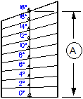
Starting height
Define the height of the stair in the global coordinate system.
When you create the stair with a starting step (see Steps area), the top edge of the starting step results from Starting height plus Rise. In this case, Allplan assumes that the floor covering at the lower stair connection is the same thickness as a tread.
When you create the stair without a starting step, the starting height is the top edge of the first stair component or the top edge of a tread.
Height difference
Define the height difference between the starting step and the last step or between the Starting height and the height of the top edge of the last stair component.
Number of steps
Define the number of steps (= rise) for the entire stair.
Rise
Define the rise of one step; measured vertically from the top edge of one step to the top edge of the next step.
Tread
Define the tread of one step; measured horizontally from the front edge of one step to the front edge of the next step.
2 x R+T
Define the tread-to-riser ratio of Tread and Rise (usually 590 - 650 mm).
Width
Define the width of the flight of stairs.
Axis position
Define the position of the stair axis in relation to the walking direction.
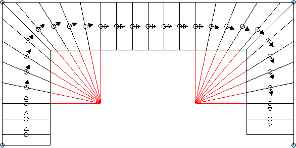
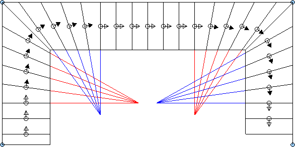
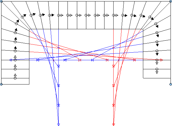
Skew
Skew is the term used to describe a stair where the orientation of the front edge of each step deviates from that of the previous step by a specific angle.
First, the program identifies the difference between the angles of the starting step and the last step, distributing this angle evenly to all steps. If you locked some steps, the program calculates the angle and the skew between two locked steps.
Method
Select the skew method you want to use.
You can choose from three numeric methods and three geometric methods:
Geometry
Select this check box to display the geometric structure used for skewing. This is only possible for the geometric skew methods.
Steps
Define the number of steps you want to skew together.
Min. tread
Define the minimum tread run for skewing.
Stair
Complete
Select this check box to create all components of the stair based on the parameters defined in the Dimensions area. Otherwise, the stair ends at the last axis point of the stair axis.
For example, select this check box if you want to calculate the slab opening based on the stair.
Axis
Only available when you modify an axisymmetric stair.
You can adjust the stair outline axisymmetrically.
Landing
Only available when you design a new stair.
Select this option if you want to insert a landing after the Max. number of steps defined.
Max. number of steps
Only if the Landing option is selected
Enter the number of steps after which you want to insert a landing automatically.
Landing length
Only if the Landing option is selected
Enter the length of the landing.
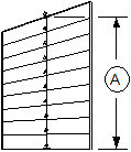
Flight
Last step
Select this check box to lengthen the last step as far as the last axis point of the stair axis.
Steps
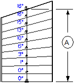
Starting steps
Create or remove a starting step as the first stair component; the step gets the Rise defined.
Last steps
Create or remove a last step as the last stair component; the step gets the Rise defined.
Representation
2D representation
Select this check box to display the stair in plan.
You define the settings for plan view on the Plan view tab.
A stair element is only visible in plan when you select the Create check box in the 2D representation area on the tab of the stair element.
Note: If the 3D representation of the stair is not selected, the tabs for the stair elements are not visible. Select the Create 3D representation check box and open the tab of the stair element. Select or clear the Create check box in the 2D representation area on the tab of the stair element. Finally, clear the Create 3D representation check box on the Settings tab again.
3D representation
Select this check box to display the stair in elevation and perspective view.
Select the stair elements you want to display in 3D on the Elements tab.
Headroom clearance
Select this check box to check the stair design based on a headroom clearance.
Enter the dimensions of the headroom clearance on the Clearance tab.
| (C) ALLPLAN GmbH | Datenschutzbestimmungen |