![]() Catalogs for precast concrete elements
Catalogs for precast concrete elements
You can use this catalog to define default settings for the generation of production data by means of the ![]() Production Data, NC Generator tool.
Production Data, NC Generator tool.
![]() "Data creation" tab
"Data creation" tab
Created on:
Date the record was created.
Last modified:
Date the record was last changed.
Name:
User-defined name that is visible in the list box for driver selection in the NC Generator dialog box.
Description:
User-defined name that is visible in the lower-right area of the Driver/order data tab in the NC Generator dialog box.
Driver:
Selection of Unitechnik driver. which is visible in the lower-right area of the Driver/order data tab in the NC Generator dialog box.
If you want to create the data in PXML format, select the ProgressXML entry.
Note: If you use the![]() PTS Server Control function, please note you must create at least one driver in PXML format which can be referred to in the PTS catalog.
PTS Server Control function, please note you must create at least one driver in PXML format which can be referred to in the PTS catalog.
Coding:
Use ASCII coding to create the file for the Unitechnik driver in accordance with the interface. You can also use ANSI code. Discuss this with your data exchange partner and agree on the coding type.
The ASCII/Multibyte setting is intended for Asia. In ASCII a character has 1 byte, whereas Chinese characters use up to 4 bytes. Select this setting to count multibyte characters with a length of 1. As a result, these characters can be represented in ASCII.
The ProgressXML driver uses a fixed coding in UTF-8.
Graphical representation of data:
2D, 3D front left, 3D front right
Default setting for graphically displaying the elements in the upper-right window of the NcGenerator dialog box. When you select 3D, you can display the element in an isometric view from the front left or front right.
Tip: You can link the graphical representation on the screen with the driver: If you need different drivers, select a different option for each driver. So, you can see at once which driver is the current one.
Production data path
The program writes the data for machine control in the selected Folder and Subfolder defined by the Variable and Pattern. You can specify any path, including network paths. The program displays an error message when the folder does not exist. If a subfolder does not exist, the program automatically creates it.
Note: Define the Pattern and Variable for the Subfolder in accordance with the following rules for file names.
Production file – naming convention
Rules for creating file names.
Pattern: Enter the required name. Use formatting characters to enter the variable values as placeholders. The program replaces the formatting characters with the corresponding values. Enter the formatting characters as follows:
%s: for strings
%d: for integers
%f: for floating point numbers
You can also define how to output strings and numbers:
%10s: Returns at least 10 characters (with spaces).
%-10s: as shown, left-aligned.
When you enter a point (".") between "%" and the number, the resulting string is truncated to the number specified.
For example, entering %.4s changes the "1234567" string to "1234".
%3d: Returns at least 3 characters (with spaces).
%03d: as shown; however, zeros (for example, 002) are added.
%.3f: output of 3 decimal places.
%6.3f: output of a total of 6 characters (including decimal point) and 3 decimal places.
Variable: Enter an arithmetical expression for each wildcard character. Use "," as a separator. Arithmetical expressions can be arithmetical operators, numbers, and variables. You can click on the Variable button to enter possible variables. This opens a dialog box where these possible variables will be displayed. Alternatively, you can manually enter the variables directly.
Delete files
Specify which files you want to delete from the path before creating production data. To do this, define the Pattern and Variable in accordance with the rules for file names.
Note: As the program deletes the files before creating new files, the element variables (for example, MrkNo) are not available. Consequently, you cannot use these variables for defining the Pattern. As a result, the program can delete files only if the pattern does not use these variables.
![]() "PXML" tab
"PXML" tab
The settings on this tab are only available when ProgressXML 1.3 is selected for the Driver on the Data creation tab. You can use the options to specify accompanying information (so-called Mode Directives) for the data recipient. These settings indicate how you want to use the file, but they do not affect the actual contents of the file.
Indicate output mode
Production:
When you select the Directive, an unrestricted production release is then issued for the relevant data. The contents of the file are intended for production. This Directive is used to distinguish between final CAD data (with production release granted) and previous versions of the same data.
Reinforcement:
This Directive is similar to the Production Directive, but it does not allow for the release to apply to reinforcement production. The PTS server is to check whether the contents of the file can be produced. This Directive is of particular use for systems that require a longer lead time to prepare the reinforcement. This is because reinforcement production may potentially have to commence prior to the final drawing release being granted.
Materials management:
This Directive is similar to the Production Directive, but it does not allow for the release to apply to material procurement. The contents of the file is intended for materials management or invoicing by an ERP system.
![]() "PXML extensions" tab
"PXML extensions" tab
The settings on this tab are only available when ProgressXML 1.3 is selected for the Driver on the Data creation tab. When this driver is selected, you can configure the program to create PXML Delegate Files when creating the production data. By means of these files, you can merge information from the ERP system, such as data for the order header (order number, customer information, delivery date and so on) and the article list with CAD information (geometric data).
The PXML Delegate File V 1.3 lists in ![]() List Generator, on the other hand, contain only the data for the order header and the article list of the KST file. You must create the production data manually in a second step for these lists.
List Generator, on the other hand, contain only the data for the order header and the article list of the KST file. You must create the production data manually in a second step for these lists.
You can create PXML data with detailed geometric information in two ways:
Create PXML Delegate File
Select the check box to create PXML Delegate Files. Under List folder, select the folder (Default or Office) with the form for creating PXML Delegate Files and select the required form.
Prompt before processing lists
Select this check box to define separate prompt templates for Slab lists, Wall lists, and St(ructural)Pr(ecast parts) lists. The program displays these prompts before creating the PXML Delegate Files.
Merge PXML Delegate Files:
Delegate File is the PXML file that the list generator creates with the contents for materials management. The list generator always creates this file with all elements for each project. The NC generator, on the other hand, always creates this file for each precast element because this is required for import by the control computer. If everything was transferred completely (that is, production data and materials management) to a system, this would lead to problems because the NC generator cannot process the commercial data and the list generator cannot create production data. Therefore, the list generator creates the "Delegate" file first and then the NC generator creates the production files.
You can use the following setting to define the structure of the file. You can choose between the following options:
When you select the Remove invalid product entries check box, the program deletes invalid nodes from the PXML Delegate File. For example, this option is useful when you integrate a PXML Delegate File created by a different software program instead of generating the PXML Delegate File together with the production data.
![]() "Mirroring/structure'" tab
"Mirroring/structure'" tab
You can define the following parameters for the element selected in the left list if a Unitechnik driver is selected on the Data creation tab.
Note: If production data are generated for wall elements created using ![]() Design (iWall), and where the production sequence was switched over, these elements will be turned over accordingly on the palette to ensure the geometry, recesses, reinforcement, and so on are in the correct position. In the case of double and thermal walls produced using the 2-tier setting, they will be assigned to the corresponding leaf.
Design (iWall), and where the production sequence was switched over, these elements will be turned over accordingly on the palette to ensure the geometry, recesses, reinforcement, and so on are in the correct position. In the case of double and thermal walls produced using the 2-tier setting, they will be assigned to the corresponding leaf.
When you have selected a ProgressXML driver, you cannot change the settings because there is only one correct option in accordance with the definition. In the case of double walls and thermal walls, the program displays the leaves as they are initially (= before turning) placed on the pallets.
Data structures
All elements except concrete slabs, concrete walls, sandwich walls, structural precast elements and precast elements:
The default structure always applies to these elements. Double walls and thermal walls get two files: one for first production (leaf 1) and another one for second production (leaf 2). The insulating layer will be transferred as a surface fixture (if a reference fixture is defined in the insulation material catalog). The outline of the insulating layer results from the shadow areas of the layers.
Concrete slab, concrete wall and sandwich wall:
Default: Unitechnik default structure (see interface definition). This means that the multilayer sandwich wall element will be written to a single file. The layers will be filled out in the SLABDATE block. All the leaves will be transferred to the CONTOUR blocks. The outlines of the panel parts that are not on the formwork get the "special formwork" edge attribute.
3D polyhedron: default structure; 3D data will be created in addition to the geometric data in 2D. The data is not in accordance with the current requirements of the interface. You must discuss this issue with your data exchange partner in advance.
Structural precast elements:
Default: Unitechnik default structure (see interface definition)
Layer/lot: Unitechnik layer/lot structure (see interface definition):
By default, two layers will be created for each structural precast element. The bottom layer contains the lowest area of the precast element and the component thickness of the entire element as a lot (outline). The lowest area must be flat on the formwork, that is to say, the direction vector must be perpendicular to this area.
In addition, a layer with a thickness of 0 will be transferred. This layer includes the topmost area of the element.
You can specify your own cutting planes by entering z-coordinates. In this case, the element will be cut at the z-height specified and the cut area will be transferred as a layer. The thickness will be measured at the height of the cutting planes.
A further division into lots is currently not implemented. A lot always contains all polylines as outlines. These polylines result from the cut at the corresponding height.
Based on the z-coordinates, the program assigns fixtures and bar reinforcement to the layers. This is necessary for leveling and cutting systems. All other elements (lattice girders, attached reinforcement and so on) will be transferred in the first layer.
3D polyhedron: default structure; 3D data will be created in addition to the geometric data in 2D. The data is not in accordance with the current requirements of the interface. You must discuss this issue with your data exchange partner in advance.
Precast Elements:
The default structure applies to precast elements. There is no defined setting for mirroring coordinates, as is also the case with the settings for the pallet width or the stop on pallet.
Mirroring coordinates
None, x-direction, y-direction, x+y-directions
You can mirror the coordinates of the individual elements. This also defines the origin from which the coordinates are measured.
Pallet width for calculation of y-offset when mirroring:
When transferring data by panel, the program uses this offset to calculate leaf 2.
Stop on pallet:
Simulates the position on the pallet when data is transferred panel by panel. The Top setting rotates the entire element (that is to say, first production and second production for two leaves) by 180 degrees upward to the pallet width. Geometrically speaking, this is the same as mirroring the coordinates in the x+y-directions. Consequently, when it comes to geometry, there is no difference between the "Top" and "Mirroring - x+y-directions" settings. However, the "Top" setting adds an angle of 180° to the SLABDATE block (rotation on pallet), which results in angles of 270° or 90° for extra-high walls.
Note: As the program considers both Mirroring coordinates and Stop on pallet, the two options might cancel each other out! This results in the original data, but the rotation angle is 180°.
![]() "Element data" tab
"Element data" tab
Element data
Element name:
The mark number or mark number text will be written to the interface so that the element can be identified uniquely in a database.
Overwrite product codes
You can freely define the product codes (for example, 0 for half floor) that are specified in the interface. You can give each precast element type its own product number by doing the following:
To delete a product number, select the assignment in the list and click the Delete button.
Note: A structural precast element always consists of an exact type (for example, Column) and a general type (Structural precast elements). When you use the general type, this type applies to all structural precast elements. If there is an additional assignment for a special type, this assignment has priority over the general type.
If there are several assignments for a type, the program always uses the first assignment.
![]() "Geometry" tab
"Geometry" tab
Remove points on continuous lines
Points on straight lines will be removed.
Element geometry encloses recesses at panel edge
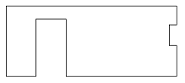
If this check box is selected, recesses at the edge of an element do not intersect the outline of the element; that is to say, the original outline of the element remains unchanged.
Attention: If you create an architectural opening that projects beyond the element, the element will be enlarged by the projecting opening!
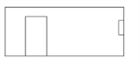
It this check box is not selected, the outline looks like this:
Consider protruding parts with max. element size
The program recalculates the maximum element size for protruding parts of the selected type. In addition, it recalculates the coordinates of the data. The parameters of the fixture catalog apply to fixtures.
Bar reinforcement must penetrate the element edge so that the element dimensions will be enlarged! In other words, a cranked bending shape that projects beyond the panel edge has no effect on the element size!
PXML geometric data (SVertex):
This parameter is only available when ProgressXML 1.3 is selected for the Driver on the Data creation tab. You can use this setting to define how to transfer sloping edges (for example, of prisms or polyhedrons) to production. You can choose to create the data as a Shadow (2D) or by using the Advanced vertices, polyhedron splitting (3D) option.
![]() "Line attributes" tab
"Line attributes" tab
Poured joints for concrete walls
Add edge attribute (bit 2) to poured joints at wall ends
In the case of poured joints at concrete wall ends, poured joint attributes can be added to these panel edges.
If this check box is not selected, the poured joint bit will not be set. Otherwise, the following options are available:
Add only: The program sets a poured joint bit without changing the chamfer attributes transferred from Allplan.
Set chamfers: The program sets a poured joint bit and chamfer attributes at the top and bottom (Unitechnik bit mask = 0004, unless other bits are set in addition).
Delete chamfers: The program sets a poured joint bit and deletes chamfer attributes from the top and bottom (Unitechnik bit mask = 000D, unless other bits are set in addition).
Attribute manipulation
You can use this option to modify specific edge attributes. In other words, you can switch an attribute to a specific value that is not available in the CAD program. There are three lines you can use to define the attributes that you want to replace with different values.
Explanation of the fields:
Use decimal notation to enter the attributes and bit masks in the mask.
|
Bit number |
Description |
Decimal |
Hexadecimal |
|
0 |
No chamfer at bottom |
1 |
0x01 |
|
1 |
Special formwork |
2 |
0x02 |
|
2 |
Poured joint |
4 |
0x04 |
|
3 |
No chamfer at top |
8 |
0x08 |
|
4 |
Rounding off at bottom |
16 |
0x10 |
|
5 |
Spring |
32 |
0x20 |
|
6 |
Groove |
64 |
0x40 |
|
7 |
Rounding off at top |
128 |
0x80 |
(The attributes are specified in hexadecimal notation in the interface.)
Example of attribute manipulation
![]() "Fixtures" tab
"Fixtures" tab
Create fixture data
You can configure the program not to create any fixture data at all.
Fixture name:
Specify whether to use the reference text or list text. This depends on the method your data exchange partner uses to analyze the data. The info text contains the other name, which is not used.
Create center of gravity for wall as a fixture:
You can create a fixture as a substitute symbol in the wall's center of gravity. The program calculates the center of gravity from all layers or concrete areas. You can freely define the name of the fixture or select it from the fixture catalog by using the list box.
When you select a symbol fixture defined in the fixture catalog, you can control the substitute symbol, its size, and other parameters (settings on the Prod. internal tab). When you enter a text only, the program creates the fixture based on fixed default values.
Create layer symbol for slab as a fixture:
You can create a fixture as a substitute symbol for the slab's layer symbol (lower-left corner of the element in the placing drawing). The program first defines the lower-left corner (min.y, min.x). Then, it calculates the symbol based on the parallel distance from the edges (offset = x size of symbol). You can freely define the name of the fixture or select it from the fixture catalog by using the list box.
When you select a symbol fixture defined in the fixture catalog, you can control the substitute symbol, its size, and other parameters (settings on the Prod. internal tab). When you enter a text only, the program creates the fixture based on fixed default values.
Create wall upstands as fixtures:
Architectural upstands of walls can be transferred as separate fixtures. You can freely define the name of the fixture or select it from the fixture catalog by using the list box. In the latter case, the program also correctly transfers the "type and code" values from the catalog.
Note that it is not possible to exactly display upstands around corners or 3D geometries because fixtures in the Unitechnik CAD-CAM interface are merely defined by a polygon consisting of the z-dimension and the thickness.
Create poured joints as fixtures:
Poured joints in walls can be transferred as separate fixtures. You can freely define the name of the fixture or select it from the fixture catalog by using the list box. In the latter case, the program also correctly transfers the "type and code" values from the catalog.
Note that it is not possible to exactly display 3D geometries because fixtures in the Unitechnik CAD-CAM interface are merely defined by a polygon consisting of the z-dimension and the thickness.
Create shuttering objects as fixtures:
You can transfer shuttering objects for multilayer walls separately as fixtures. The program uses the fixture only to compute concrete distribution, making sure the right places get the necessary amount of concrete. You can freely define the name of the fixture or select it from the fixture catalog by using the list box. In the latter case, the program also correctly transfers the "type and code" values from the catalog. In addition, the formwork attributes defined using Set formwork attributes: CONTOUR) will be used.
Note that it is not possible to exactly display 3D geometries because fixtures in the Unitechnik CAD-CAM interface are merely defined by a polygon consisting of the z-dimension and the thickness. At the z-coordinate, the shuttering objects must be split based on the existing layers. Sloping objects must be converted to boxes of the same volume and outline (seen from the top); that is, the concrete volume and the outline for the concrete distributor must be correct.
Moreover, a general algorithm looks for differences in the polyhedrons of the layers. This might result in fixtures that do not match the expectations of the processing software.
Create stirrup cages as fixtures:
Min-max boxes of stirrup cages can be transferred as separate fixtures. This makes it easier for the control computer to check for collisions with other components because the exact position of bent reinforcing bars is not always defined clearly by the Unitechnik CAD-CAM interface.
You can freely define the name of the fixture or select it from the fixture catalog by using the list box. In the latter case, the program also correctly transfers the "type and code" values from the catalog.
Create lattice girders as fixtures:
Lattice girders will be transferred as fixtures. You can reference an entry in the fixture catalog or freely define the name. When you use a catalog reference, some parameters will be taken from the catalog (name, type and code, info text).
You have the following options to generate geometrical data (for the plotter or laser):
Girder marker length: Indicates the length of the girder; that is the length of the markers at the start and end of the girder. 0 prints the full girder.
Indicate girder width (bottom boom): A slash indicates the width of the girder on the side of the bottom boom.
Create in second leaf: Creates the lattice girder so that the bottom boom is in the second leaf.
![]() "Reinforcement" tab
"Reinforcement" tab
Create reinforcement data
You can configure the program not to create any reinforcement data at all.
Reinforcement system
Data structure:
This parameter is only available when a Unitechnik driver is selected on the Data creation tab.
Leveling and cutting system: The bar data will be created in the structure required for leveling and cutting systems (see Unitechnik CAD-CAM interface).
Att.reinf. + leveling, cutting: The bar data will be created in the structure required for attached reinforcement.
Lattice girders and reinforcing bars outside a reinforcement mesh will be created outside the STEELMAT blocks in the RODSTOCK and BRGIRDER blocks.
Attached reinforcement: The bar data will be created in the structure required for attached reinforcement (see Unitechnik CAD-CAM interface). Reinforcement belonging to a single mesh will be combined into a STEELMAT block. However, this is only possible if the reinforcement data was created by the Optima generator.
Remark: Lattice girders and reinforcing bars outside a reinforcement mesh will be assigned geometrically to the mesh (based on the xy plane) and transferred within the STEELMAT block.
z-coordinate at bar:
This parameter is only available when a ProgressXML driver is selected on the Data creation tab.
Relative to STEELMAT: The program usually calculates the z-coordinates of the bars (RODSTOCK) based on the z-offset of the mesh. In other words, the first bar layer is always Z=0 because the concrete cover is included in the mesh offset.
Absolute: Use this to write the absolute z-coordinate (based on SLABDATE). As a result, the mesh offset in the z-direction is 0.
Turning information:
This parameter is only available when a ProgressXML driver is selected on the Data creation tab.
Deactivated: The turning flag of the mesh (indicating whether the mesh must be turned after welding) will not be set.
By span direction: The turning flag of the mesh (indicating whether the mesh must be turned after welding) will be set if the span direction is >= 45°.
By element type: The turning flag of the mesh (indicating whether the mesh must be turned after welding) will be set in accordance with the element type:
Calculate MWS cross bars of layer 2 as:
In conjunction with attached reinforcement, the exact bar type will be lost because you do not need to place any manual bars.
With this setting, you can "restore" this bar type for Optima bars that are transferred in accordance with the normal structure for leveling and cutting systems.
Meshes and bent-up meshes
Create mesh as:
Common stock mesh is usually not produced automatically and thus not included in the interface.
External mesh: stock meshes are written as external mesh (Unitechnik, "Information block EXTIRON" or PXML, "Type attribute" = "extiron").
"STEELMAT", only weight: a "STEELMAT block" (Unitechnik) or a "Steel section" with the "Type attribute" = "mesh" or "cage" (PXML) is written with the mesh data only.
Note: In Unitechnik, stapled reinforcement must be activated for the data structure .
'STEELMAT', complete geometry: a "STEELMAT block" (Unitechnik) or a "Steel section" with the "Type attribute" = "mesh" or "cage" (PXML) is written with the mesh data.
This is followed in Unitechnik by the "RODSTOCK blocks" or the "bar entries" in PXML, which contain the complete geometry of the bars.
The bar data can be displayed in a high-performance viewer (such as AviCAD), but is marked as "can be produced manually".
Write mesh to BVBS file (*.abs)
Like bars, stock meshes get an additional *.abs file including the BVBS string. Unlike bars, where the *.abs file only includes the bars that cannot be produced, stock meshes will always be written to the *.abs file. The reason for this is that stock meshes are in stock and thus not produced individually. Consequently, stock meshes are always considered not to be producible.
Custom MWS meshes, reinforcement groups
Calculate bar type based on layer
You can use this parameter to grade bars of free reinforcing meshes that are not linked with a precast element. These bars belong to straight meshes of attached reinforcement created with the ![]() Use MWS mesh setting in the Mesh Reinforcement task area (Engineering role).
Use MWS mesh setting in the Mesh Reinforcement task area (Engineering role).
When you select this check box, the program defines the Reinforcement type of the bars (1st bar layer, 2nd bar layer, value 3 in line 4 of the RODSTOCK block) in accordance with the height settings of the bars.
If the mesh does not have a cross bar whose z-minimum is less than or equal to the z-minimum of the longitudinal bars, the program corrects the reinforcement types of the longitudinal bars and cross bars. Consequently, the longitudinal bars are of reinforcement type 1 or 5 and the cross bars of type 2 or 6.
When this check box is not selected, the program always assigns the bars in accordance with their functions as cross bars and longitudinal bars to the 1, first bar layer (formerly cross reinforcement) and 2, second bar layer (formerly longitudinal reinforcement) reinforcement types in a fixed manner.
Note: The Place in bundles and Produce with leaf 1 parameters (Is it possible to produce reinforcement? dialog box) apply to the corrected bar because the program bundles or moves the bars to another leaf at the very end.
The same applies to sorting: As the program sorts the bars at the very end, the corrected reinforcement type applies instead of the actual bar type.
Rotate mesh in base position
With this option, you can rotate the meshes to their base position if necessary. Base layer refers to the plane in which the defined base section is located. However, this only applies to groups that are in a precast element, since freely transferred groups are rotated to their base position anyway.
Note: This box is only selected if you have selected one of the Stapl.reinf. + leveling + cutting or Attached reinforcement options for the data structure. The option is always active and grayed out for Leveling + cutting system.
![]() "Producible?" tab
"Producible?" tab
Producible diameters [mm]
Specify the diameters that can be processed by the machine. You must do this separately for Cross-bar diameters and Longitudinal-bar and secondary-bar diameters.
You can enter one or more values. For example: 6, or 6,8,10, or 0-99,.
Nonproducible diameters
These are the diameters that cannot be produced in accordance with the configuration.
Write with manual production flag
The bars will be written with No automatic production identifiers to the Unitechnik file or PXML file.
If you do not select this option, the bars will not be written to the file.
Create additional BVBS file
The program creates an additional BVBS file with the nonproducible bars for each element. So, the bars can be produced separately by a machine. The name of the file is identical to that of the Unitechnik/PXML file; the extension is *.abs.
Warning
If the element has a nonproducible bar, the dialog box of the NC generator displays a warning.
![]() "Filter" tab
"Filter" tab
Basically, all bar types can be produced. This is predefined in the default settings.
If bars are to differ from these default settings, you must define the different settings here. By using freely definable filter settings, you can exclude bar types from production. You can freely combine these filters, which contain different criteria.
This tab has three areas:
Name of filter:
You can freely enter any name. This name helps you identify the filter.
Filter conditions
Use Filter conditions to define the settings that differ from the default for creating production data. You can make separate settings for each bar type, specifying whether and how to produce this type. The settings in detail:
Bar type:
Define the bar type to which the filter is to apply. You can choose from the following types of reinforcement:
not defined: The filter applies to all bars
Longitudinal bars: Bars of basic reinforcement
Cross bars: Bars of basic reinforcement
Secondary bars of standard shape: Secondary bars of reinforcement at bottom or top
Secondary bars of any shape: Freeform secondary reinforcement (reinforcement created in Engineering)
Secondary bars of any 3D shape,
Secondary bars of round shape,
Stirrups: Stirrups of a stirrup cage
Stirrup longitudinal bars: Secondary stirrups of a stirrup cage or of bent-up meshes
Reinforcement groups
Loose MWS bars: Loose bars of attached reinforcement
Lifting bolts
Note: You can use a special filter to select the reinforcement in the Core concrete layer of a thermal wall with an in-situ concrete core.
Position of reinforcement:
Bottom+top, Bottom, Top
This option is only available for the following three bar types: Longitudinal bars, Cross bars, and Secondary bars of standard shape.
Note: The NC generator does not compute the Position of reinforcement. Instead, it is based on the settings that you define when you create the reinforcement.
Reinforcement type:
MWS or unattached reinf.: This filter applies to both attached bars and unattached bars.
Unattached reinforcement: This filter applies to unattached bars only.
MWS reinforcement: This filter applies to MWS bars only.
You cannot use this filter criterion with the following bar types:
Secondary bars of any shape, Secondary bars of any 3D shape, Secondary bars of round shape, and Lifting bolts. These types of secondary reinforcement are never created as attached reinforcement. In this case, the fixed setting of the filter is Unattached reinforcement.
Reinforcement groups and Loose MWS bars. These reinforcement types are always MWS bars. In this case, the fixed setting of the filter is MWS reinforcement.
In leaf:
Leaf 1, Leaf 2, Leaves 1+2, Core concrete layer
Define the production leaf that contains the bar type.
For example, you can configure the program to separately process the leaves or to write the bars to a different leaf.
Core reinforcement has a special status. As these bars do not belong to any leaf, you can define a filter that writes these bars to a producible leaf. As an alternative, you can also transfer core reinforcement in the Concrete core layer.
Number / Layer:
This option is only available for the following three bar types: Longitudinal bars, Cross bars, and Secondary bars of standard shape.
In accordance with the reinforcement type catalogs for slabs, you can enter up to three diameters (first, second, third layer) for the longitudinal bars at the bottom and up to two diameters (first, second layer) for the cross bars at the bottom and top. In the case of walls, you can enter up to three diameters (first, second, third layer) on both sides. Use Number to define for which of these diameters the entry is to apply.
Use Layer to sort all bars of basic reinforcement based on the ascending z-coordinate. Afterward, the program groups the bars of each reinforcement unit (reinforcement at bottom, in-situ concrete, reinforcement at top) in accordance with their heights and numbers these groups, starting at 1.
Bar lengths [m]:
You can define certain bar lengths that cannot be produced for the selected bar type. Thus, you can exclude specific bars from production such as prefabricated cross bars.
You can enter one or more values. For example: 0-0.199 or 0-0.199, 2.485, and so on.
Wire diameter [mm]:
You can exclude certain nonproducible diameters from the production data file.
Filter / Change / Parameter
Write:
Choose to write the bar to the production file.
No: Bars will not be written to the Unitechnik file or PXML file.
Yes: Bars marked as can be produced automatically will be written to the Unitechnik file or PXML file. However, this only applies to bars that can be produced!
Yes, produce manually: Bars that are not producible will be written with "manual production flags" to the Unitechnik file or PXML file. The control computer does not transfer these bars to the machine. Instead, the bars must be cut and placed manually. The data is mainly used for materials management.
Bending definition:
You can select the variant of bending definition. This is only possible when at least two variants are available.
Default: Parameterized default bending shapes. The PXML file transfers default bending shapes as custom bending shapes.
Bent: Custom bending shapes in accordance with the Unitechnik CAD-CAM interface.
Bending data of attached stirrup cages will be transferred as custom bending shapes without special specifications for Progress. This transfer type cannot be used with Filzmoser machines.
Length before bending: Custom bars will be transferred without bends (actual length). Longitudinal bars and cross bars of reinforcement groups (attached cages) can be unfolded (length before bending) for transfer. If cross bars and/or longitudinal bars are attached (welded) to the unfolded segments, the program calculates the new positions accordingly, including the bending radii. As a result, the mesh welding system can produce the bars.
Length before bending, longitudinal: Longitudinal bars of reinforcement groups (attached cages) are unfolded (length before bending) for transfer. If cross bars are attached (welded) to the unfolded segments, the program calculates the new positions accordingly, including the bending radii.
Length before bending cross: Same as before, albeit with stretched (unrolled) cross bars and new position calculation for longitudinal bars welded to the stretched legs, where applicable.
Produce in leaf:
Do not change leaf, Leaf 1, Leaf 2, separate file
This setting applies to precast elements with two leaves (double wall, thermal wall). You can decide to produce the bars of leaf 2 in leaf 1.
Core reinforcement (reinforcement of a thermal wall with an in-situ concrete core) can be produced in leaf 1, leaf 2, or in a separate file. The name of this file results from the name and extension of the production data file (defined as Name on the Data creation tab) plus the additional extension *.bew.
In addition to the Do not change leaf option, you can also produce in Leaf 1 or Leaf 2 for MWS reinforcement groups. A separate file can also be generated here. However, unlike the core reinforcement, the file names are already pre-defined in the Filename/templ.:. field. Here you can define a template for the file name of the reinforcement cage file, analogous to the file name for the production data on the Data creation tab. Clicking the button behind the input field opens a sub-dialog where you can define the Template and the Variable for the creation of the file name. The GrpNr (Number of reinforcement group) and BTName (Name of reinforcement group) variables in particular are provided here for this purpose.
Lock bar type:
You can force the program to use a specific bar type. So, you can always transfer specific bars with the same bar type even if this type is not appropriate.
Note: As opposed to the Unitechnik CAD-CAM or PXML interface, 0 does not stand for the "without definition" setting. Instead, 0 transfers the bars with the bar type that is based on the settings that you define when you create the reinforcement. Please note this option is not available for reinforcement groups.
Warning
If an element has nonproducible bar types of this category, you can see a warning in the dialog box of the ![]() Production Data, NC Generator tool.
Production Data, NC Generator tool.
Write to BVBS file
The program creates an additional BVBS file with the nonproducible bars for each element. So, the bars can be produced separately by a machine. The name of the file is identical to that of the Unitechnik/PXML file; the extension is *.abs.
Place in bundles
The program changes the bar coordinates to a specific, predefined value. These bars will then be placed by hand.
Correct angle:
This option is only available for the Reinforcement groups bar type.
When you select this parameter, custom bending definitions in accordance with the Unitechnik CAD-CAM interface include a pseudo-segment of zero length and a specific angle for rotating the bending plane.
This is a special way of transferring bending data of attached stirrup cages, making it possible to calculate the exact bar position in 3D. This setting applies only to special systems of the Progress company (this is not an interface standard). Some fields in the RODSTOCK record get special assignments; data will be transferred in the BENDING RECORD FOR CUSTOM BENDING SHAPES.
![]() "Bundling" tab
"Bundling" tab
Insertion angle for bar robot; Wall / Slab:
This setting tells the NC generator which insertion angles are valid.
Bundle:
Specify whether the bars are placed in a "bundled" manner. "Bundled" means that all bars will be placed on one (specific) coordinate. These bars will then be placed by hand. (e.g. "Bars placed by hand")
Produce in leaf 1:
The bars of leaf 2 will be transferred in leaf 1.
![]() "Placement" tab
"Placement" tab
Place bundled bars
Placing coordinates:
You can specify the placing coordinates of bundled bars in the x-direction and y-direction.
Placing height (z-coordinate):
The specified height will be transferred as the z-coordinate. This is important if the bundled bars will be placed above the cross shutter, making sure the arm of the reinforcement robot will not be damaged.
Switch insertion angle to 0 degrees
The program usually transfers the actual angle of the bundled bars. When you select the Set insertion angle to 0 degrees check box, the program recalculates the insertion angle, switching it to 0 degrees. This setting is required by some machines (Filzmoser), so that the robot can place 2 bars at once (with the double grab). However, other machines require the real insertion angle (not equal to 0 degrees), so that they can recognize bars that cannot be placed.
![]() "Sorting" tab
"Sorting" tab
You can define how to sort the bar data.
Sort sequence / Sorting
Select an entry in the left table and edit it by using the buttons to the right of the table. You can move the entry up or down, sort the entries in ascending or descending order, and turn the sorting criterion on or off.
Use the tools to the right of the table to make the highlighted entry![]() Move up,
Move up,![]() Move down
Move down![]() , Sort in ascending order or Sort in descending order. You can also
, Sort in ascending order or Sort in descending order. You can also ![]() Select the sorting criterion or Disable the sorting criterion.
Select the sorting criterion or Disable the sorting criterion.
Sequence numbers for bar type
When the bars are sorted by bar type, you can specify which bar type has priority by assigning a number.
You can change these numbers by selecting the number of the required bar type in the list and clicking the number to change it.
Band width for x-coordinate/y-coordinate:
The program turns off sorting by coordinates in the bandwidth specified to prefer the next priority if there are slight differences (for example, slightly sloping edges).
Compress reinforcement elements
This parameter is only available when a Unitechnik driver is selected on the Data creation tab.
Bars of the same length and diameter that are parallel to one another on the pallet will not be transferred individually but based on the number of pieces or distance. This considerably reduces the volume of data. By selecting this option, you can reduce 35 data blocks of cross bars to 1 data block, for example.
Max. spacing for division [mm]:
You can specify the maximum spacing (parallel offset) between the elements to be compressed.
![]() "Spacer" tab
"Spacer" tab
You can specify how to calculate spacers for which bars.
Transfer spacers
Longitudinal bars:
Spacers will be calculated for the longitudinal bars.
Cross bars:
Spacers will be calculated for the cross bars, layers 1 and 2 (bars placed manually).
Spacer type:
The spacer type will be calculated based on the concrete cover. You specify the type by entering a specific region (from - to). The height of the spacer is usually the type times 5.
Example: Type 3: 0.0 - 19.0; Type 4: 20.0 - 100.0
If the program cannot find a valid region, it does not transfer spacers.
Cross bars at top:
Spacers will be calculated for the cross bars at the top, layers 1 and 2 (bars placed manually).
Spacer type, top cross bars:
This type will generally be transferred for the cross bars at the top.
Valid spacer diameters:
You can define which diameters apply to the spacers. If a diameter does not match the region specified, spacers will not be transferred.
Calculation method:
Equidistant: The spacers will be distributed evenly over the cross bars. The number of spacers results from the weight of the reinforcement supported by the cross bars and the maximum load-bearing capacity of a spacer. This is used for slab elements and wall elements of second production.
Lock girder: The spacers will be placed alternately to the left and right of the lattice girder. This is used for wall elements of first production.
Offset info:
This parameter is only available when a Unitechnik driver is selected on the Data creation tab.
Short: Transfers the spacer type, edge offset, and axis offset.
Long: Transfers each spacer mark (only required if you do not use the "equidistant" method!)
![]() "Spacer parameters" tab
"Spacer parameters" tab
Special information about the spacer. In accordance with the calculation method selected, you can use the following parameters:
Number
Min. / Max. number per bar:
You can use up to 20 spacers.
Max. number per edge bar:
You can use up to 150 spacers.
Offsets
Min. edge distance:
Minimum distance between spacers and edge.
Min. / Max. offset:
Limits defining the spacing between the spacers.
Load-bearing capacity
Max. load capacity of a spacer [kg]:
This value controls the number of spacers: The program calculates the number of spacers from the load-bearing capacity of the spacers and the weight of the reinforcement applied to a panel. Of course, the other parameters have priority.
Note:
If there are too many or too few spacers, change the setting defining the load-bearing capacity.
Parameters for 'Lock girders'
Min. offset to bar:
Min. offset to girder slab:
Min. offset to girder at wall leaf 1:
Min. offset to girder at wall leaf 2:
These settings apply only to the "Lock girder" calculation method.
![]() "Lattice girders" tab
"Lattice girders" tab
Produce standard girders
Produce shear girders
Produce secondary girders
You can specify which girders can be produced.
Transfer dominating girder type only
If a panel contains different types of lattice girder (for example, shear girders or secondary girders), the program transfers only the most common girder type to the machine, thus avoiding delays caused by breaks in production.
Insertion angle for wall robot / slab robot:
Enter the insertion angle. You can enter one or more values. For example: 0, or 0,90,
Filter
Producible heights of girders:
You can exclude lattice girders from production based on their heights (as entered in the lattice girder catalog).
Enter the values in [mm]. You can enter several values. For example: 100,120,140,160,
Nonproducible lengths:
You can exclude lattice girders from production based on their lengths (as entered in the lattice girder catalog).
You can enter one or more values. For example: 0-0.199, or 0-0.199, 0.40,
![]() "Sorting" tab
"Sorting" tab
You can define how to sort the lattice girder data.
Sort sequence / Sorting
Select an entry in the left table and edit it by using the buttons to the right of the table. You can move the entry up or down, sort the entries in ascending or descending order, and turn the sorting criterion on or off.
Use the tools to the right of the table to make the highlighted entry![]() Move up,
Move up,![]() Move down
Move down![]() , Sort in ascending order or Sort in descending order. You can also
, Sort in ascending order or Sort in descending order. You can also ![]() Select the sorting criterion or Disable the sorting criterion.
Select the sorting criterion or Disable the sorting criterion.
Sequence numbers for girder type
When the girders are sorted by type, you can specify which girder type has priority by assigning a number.
You can change these numbers by selecting the number of the required girder type in the list and clicking the number to change it.
Band width for x-coordinate/y-coordinate:
The program turns off sorting by coordinates in the bandwidth specified to prefer the next priority if there are slight differences (for example, slightly sloping edges).
Compress girder data
This parameter is only available when a Unitechnik driver is selected on the Data creation tab.
Girders of the same length and diameter that are parallel to one another on the pallet will not be transferred individually but based on the number of pieces or distance. This considerably reduces the volume of data. By selecting this option, you can reduce 10 data blocks of secondary girders to 1 data block, for example.
Max. spacing for division [mm]:
You can specify the maximum spacing (parallel offset) between the elements to be compressed.
| (C) ALLPLAN GmbH | Datenschutzbestimmungen |
