![]()
![]()
|
|
|
![]() Tools: Create Section + Modify View, Section
Tools: Create Section + Modify View, Section
You can open the Generate Section or Modify Section palette as follows:
Filter
Remove/add elements
When the ![]() Create Section tool is open, click the
Create Section tool is open, click the ![]() Remove/add elements button to select all elements you do not want to display in the section. This applies to all elements in the active drawing files.
Remove/add elements button to select all elements you do not want to display in the section. This applies to all elements in the active drawing files.
The selected elements appear in the selection color. To confirm, right-click in the workspace.
When you click the button again, the elements you filtered out appear in the selection color. Click these elements and confirm by right-clicking to display these elements in the section again.
Click ![]() at the end of the button to display all elements in the section again.
at the end of the button to display all elements in the section again.
Drawing files
Select the drawing files for the section in the Select drawing file dialog box.
Note: The source drawing files must contain a clipping path. Otherwise, you cannot create a section.
Note: When you create a new section, the program has automatically selected the drawing files that are currently loaded (current drawing file and the drawing files that are open in edit mode and in reference mode).
Clipping Path
Select the clipping path you want to use.
If you work with the ![]() Create Section tool, you have the following options:
Create Section tool, you have the following options:
New...: Click this option to create a new clipping path in the current drawing file.
Select...: Click this option to select the clipping path by clicking it in the workspace or by entering its section identifier in the dialog line.
Layer
Select the layers you want to include in the section in the Layer filter dialog box. Click ![]() to reset the settings selected in the Layer filter dialog box.
to reset the settings selected in the Layer filter dialog box.
Update automatically
When you select this check box, the program updates the section automatically to reflect any changes you make to the model.
Resizing
Factor for x-direction; factor for y-direction
By entering factors, you can resize the section in the x-direction or y-direction or in both directions. A factor < 1 reduces the section; a factor > 1 enlarges the section.
Display
Anchor point for preview
If you work with the ![]() Create Section tool, click to select the anchor point for the preview of the section.
Create Section tool, click to select the anchor point for the preview of the section.
Reference scale for calculation
You can define the reference scale of the source drawing files for the hidden-line image.
Formats
Click the button to open the Formats palette, where you can define settings for the hidden-line image.
Label
Click the button to open the Label palette, where you can define settings for the section label.
Show Clipping Path
You can choose to show or hide the section object. The section object is placed on the DEFAULT layer. The section object appears on the screen, but it does not appear in printouts.
You can use the ![]() Modify Offset tool to change the extents of the section object. When you modify the model of the section object, you can use the input options to specify whether all edges are moved or the selected edge only.
Modify Offset tool to change the extents of the section object. When you modify the model of the section object, you can use the input options to specify whether all edges are moved or the selected edge only.
You can use the ![]() Show Clipping Path tool to display the section object of a section with or without the clipping path in a view or section.
Show Clipping Path tool to display the section object of a section with or without the clipping path in a view or section.
You cannot use ![]() Remove/add elements to show or hide the section object.
Remove/add elements to show or hide the section object.
Surface elements
![]() No surface elements
No surface elements
With this setting, surface elements are not visible in hidden-line images.
![]() Only fills from colors
Only fills from colors
With this setting, fills represent surface elements in hidden-line images. The element color defines the fill color. If a surface is assigned, the surface color of the corresponding 3D element defines the fill color. Any textures are ignored.
![]() Create bitmaps from textures, fills from colors
Create bitmaps from textures, fills from colors
With this setting, surface elements with textures are represented by bitmap areas in hidden-line images. Fills are applied to surfaces without textures (the fill color is derived from the element color or surface color).
Note: Bitmap areas are resized (cropped) correctly only in parallel projections (elevation and isometric views). But you can also achieve realistic images in perspective views with granular surfaces such as sand or plaster.
Consider transparency
Use Consider transparency to display surfaces to which you have assigned transparent surfaces as transparent so that hidden surfaces become visible. This parameter is only available when you have selected the Only fills from colors or Create bitmaps from textures, fills from colors setting.
Consider light
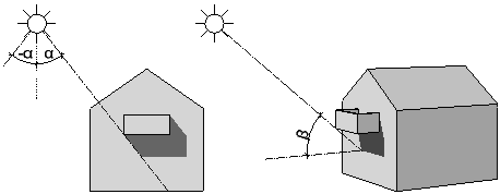
When you select the Consider light setting, the program calculates lights in hidden-line images in accordance with the settings for Light angle in view and Light angle to visible axis. This is not a sun study; the program idealizes the light situation!
Use Light angle in view (left / right) to define the direction of the shadows.
Use Light angle to visible axis (length of shadow) to define how long the shadows are.
|
|
|
alpha: light angle in view, -180° (left) to 180° (right) |
Use Light intensity to specify how many shades of color are used for fills and bitmaps. Enter a value 1 through 100 here. The smaller the value, the darker the image.
Use Fill-in light intensity to brighten up shadows and fills. Enter a value 0 through 100 here. When you specify an intensity of 0, the fill-in light is not calculated.
Select Show shadows if you want to display shadows. If you enter negative values for Light angle in view (left / right), the shadows are cast to the left. If you enter positive values, they are cast to the right. The smaller the value, the steeper the shadows. Use Light angle to visible axis (length of shadow) to control how long the shadows are in isometric views. The greater the value, the longer the shadows.
Surfaces
Click the button to open the Set Surfaces palette, where you can assign different colors to element colors. Allplan will then display the new colors - instead of the element colors - in the hidden-line image.
Result
Save
If you work with the ![]() Create Section tool, you can save the result to a different drawing file. Click the Drawing files button to open the Select destination drawing file dialog box. Select an empty drawing file for saving the hidden-line image.
Create Section tool, you can save the result to a different drawing file. Click the Drawing files button to open the Select destination drawing file dialog box. Select an empty drawing file for saving the hidden-line image.
Buttons in the border of the palette
You can find the following tools at the bottom of the palette:
|
(C) ALLPLAN GmbH |
Privacy policy |