You can change the dimensions and characteristics of all steel and timber elements.
Most parameters listed here are for the Rafters tool. You can define the parameters for the other elements in the same way.
This section also mentions special features of other elements.
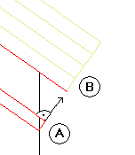
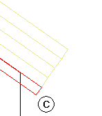
Eaves, ridge shape (for rafters, hip and valley rafters)
![]()
![]()
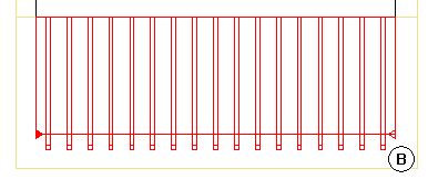
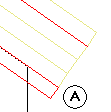
Select the manner in which the rafters end at the ridge and eaves
Cross-section (general)
Width, height |
Enter the height and width of the section as outer dimensions. Use a ”/” to separate the two values. |
Rectangle
|
You can select a rectangular section here. |
Section
|
You can select any cross-section from the library here. However, you can also create your own symbols: draw a profile cross-section as a closed 2D outline and save it as a symbol. |
Mirror, rotate
|
You can mirror or rotate the section here. |
Attributes
Material selection
Click to open the ![]() Options directly in the Component profile area. When you create timber elements with outlines saved as symbols, you can define the Number of segments by entering a value between 8 and 360; the default setting is 36.
Options directly in the Component profile area. When you create timber elements with outlines saved as symbols, you can define the Number of segments by entering a value between 8 and 360; the default setting is 36.
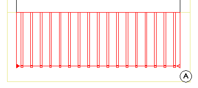
Placing parameters (general)
The relevant component is shown graphically. You can also enter dimensions here. The individual dimensions are illustrated in the preview.
Placing parameters (for rafters, hip and valley rafters, beams)
Depending on the shape you selected for the eaves and the ridge, the program displays graphics for the parameters you need to define.
When you click ![]() beside Height of TL above roof, you can specify whether the height value is to be based on the top or bottom of the component. When creating a series of rafters below a roof covering, for example, you can specify that the top level of the rafter placement is based on the bottom level of the roof covering.
beside Height of TL above roof, you can specify whether the height value is to be based on the top or bottom of the component. When creating a series of rafters below a roof covering, for example, you can specify that the top level of the rafter placement is based on the bottom level of the roof covering.
For example
When you change the Height of TL above roof value for an entire series of rafters, the program moves the rafters perpendicularly to the roof pitch, ensuring a smooth transition between the rafters and the roof covering. The position of the rafters changes accordingly in plan.
For example
Roof Pitch and Eave Height Reference Plane are locked during entry; the values they display merely reflect the settings of the roof plane or of the temporary custom reference plane.
When modifying steel and timber elements, you can enter new values for the Roof Pitch and Eave Height Reference Plane parameters and thus alter the pitch retroactively. Use this option if you have modified the roof frame by using the tools in the Roof task area you want to adjust the rafters to the changed roof frame.
The Roof pitch and Opposite pitch parameters and the Height of rafter and Height of opposite rafter values are mutually dependent. This can be produce ridges that are inclined:
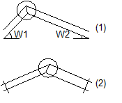
Height of opposite rafter:
(1) Inclined ridge when pitches are different
(2) Inclined ridge when rafters differ in height
Placing parameters (for rafter-supporting purlins)
You can enter an overhang at the start and end of the rafter-supporting purlin (relative to the direction in which it is entered).
The Height of TL above roof value and the Roof pitch and Eaves height of reference plane parameters work in the same way as for rafters.
Placing parameters (for posts)
You can use the Placing angle parameter to specify the angle at which the post is created in plan.
Shape (for steel, timber elements)
![]()
![]()
You can define the shape of timber elements.
Advanced attributes (for steel, timber elements)
Insertion depth (for beams)
You can define the depth by which the beam cuts through the rafter.
Surface elements in sections
These attributes control how rafters look in sections and in animation:
![]()
![]()
While defining parameters, you can save the settings in this dialog box as a favorite file or retrieve favorite files you have already saved.
|
(C) ALLPLAN GmbH |
Privacy policy |

 -->
--> 
 -->
-->