![]()
![]()
|
|
|
![]() Task area Roof + All architectural elements
Task area Roof + All architectural elements
If you do not want an element’s height to be governed by a pair of reference planes or a reference surface, you can choose to define the top level and bottom level of the element as an absolute elevation from the datum.
You can also associate the height of new architectural elements with the top level and bottom level of other elements in the workspace, or with custom pairs of reference planes already defined.
Defining the height settings of architectural elements
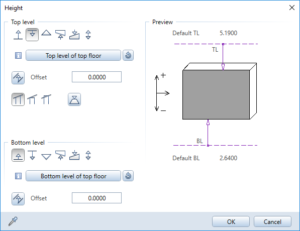
To define the height of an element, click the Height button in the ![]() Properties dialog box. You can see the Height dialog box, in which you can define the height of the element’s top and bottom levels.
Properties dialog box. You can see the Height dialog box, in which you can define the height of the element’s top and bottom levels.
Tip: Walls whose heights are defined relative to the same reference plane will intersect.
To prevent this, define the heights of the walls relative to different reference planes or enter the heights as absolute values - for example, associate the height of one wall with the upper reference plane and the height of the other wall with the lower reference plane.
Defining the top and bottom levels of an architectural element
To define the top level or bottom level of an architectural element, click the Select reference plane button and select the plane or reference surface you want to use to define the Height of the architectural element. When the project has a building structure and a plane model, you can select from all available planes, offset planes, reference surfaces, and roofscapes.
Click ![]() Restore basic settings to use the upper and lower default reference planes of the current drawing file.
Restore basic settings to use the upper and lower default reference planes of the current drawing file.
Click the required symbol in the Height dialog box and enter a value.
This ... |
Does this ... |
|
Defines the elevation of the bottom of the element as an absolute elevation relative to the datum. Possible applications: |
|
Enters the top level of the component relative to the upper or lower default reference plane. Generally, the default reference planes apply. The exception to this is when the element is located between a custom pair of reference planes or a roof frame in the same document. Note: Custom reference planes always have priority over the default reference planes. |
|
Enters the bottom level of the component relative to the upper or lower default reference plane. Here, too, the default reference planes generally apply. The exception to this is when the element is located between a custom pair of reference planes or a roof frame in the same document. |
|
Defines the top or bottom of the component by matching the values of an existing component. Click to match the settings of the architectural element. The dialog box will close temporarily so that you can do this. The angle of inclination is adopted and retained even if the reference element is deleted. Note: The reference element can be in another drawing file which is open in edit mode. Possible application: |
|
If the upper or lower custom reference plane or the top or bottom level of the reference component is inclined, you can specify how the offset is to be interpreted. |
|
Defines a fixed component height |
|
Defines the height above which the top of an element must not extend, relative to the component’s bottom level. For example, if a wall is positioned under a slanting custom reference plane, it will only follow the slope of that plane up to the point where the top level attains the maximum height specified here. Note: You cannot define a maximum component height if the height is defined as an absolute value or a fixed component height. Possible application: |
|
You can use the following options to define how the top level of a component adapts to the upper plane: |
|
Normal: This will cause the component to be drawn along the plane and ‘cut’ at an angle. |
|
Jamb wall: The lowest point where the component and reference plane intersect is locked and the component is drawn horizontally at this height. |
|
Fireplace, chimney: The top point where the component and reference plane intersect is locked and the component is drawn horizontally at this height. |
Component height, schematic overview
Reference planes in the “Height” dialog box - details
Reference planes in the “Relative height” dialog box - details
|
(C) ALLPLAN GmbH |
Privacy policy |