![]()
![]()
|
|
|
Preliminary design
2D drafts or sketches that you have entered in the Draft module form a very good basis for three-dimensional solid modeling. As the 2D elements are still missing the third dimension, you have to convert them to 3D elements first so that they can be edited in the 3D Modeling module.
To do this, use the ![]() Convert Elements tool, 2D to 3D Lines option.
Convert Elements tool, 2D to 3D Lines option.
Instead of creating 2D drafts, you can draw in 3D right from the start. To do this, you can use the ![]() 3D Line and
3D Line and ![]() 3D Surface tools you can find in the 3D Modeling module. In addition, this module offers almost all modification tools you know from the Draft module. When working in 3D, you do not have to convert the data to 3D.
3D Surface tools you can find in the 3D Modeling module. In addition, this module offers almost all modification tools you know from the Draft module. When working in 3D, you do not have to convert the data to 3D.
Designing in 3D
When designing new solids, it is best to begin on or near to the origin.
For designing in 3D, it is best if you use defined points such as the start and end points of a line, the corner or edge of a cube, or you use the tools on the Point Assistant in order to design new points based on existing ones. Also, with a suitable solid, you can enter the relevant delta X, Y and Z values starting from the global point (origin).
Snapping to existing points is easier when the workspace is divided into the standard 3-viewport arrangement: this way, you can always see the solid in plan, perspective and elevation. The 3D crosshairs that adapt intelligently to the view and the different colors used for the positive x-axis, y-axis and z-axis help you navigate in 3D space.
Preview functions provide additional support as you work in three-dimensional space: As soon as the crosshairs snap or align to a defined point, a preview of the 3D element is displayed.
Don't forget: all roads lead to Rome! There are usually several ways of obtaining the same solid. Experiment with the tools until you find what works best for you!
Editing elements
Determining exact values and angles when resizing and rotating 3D solids can sometimes be a difficult operation; moreover, the elements frequently need to be joined with others. Special 3D tools are provided for resizing and rotating operations; they work on the basis of fixed points, direction points and reference lines – i.e. it is not necessary to enter exact values.
Often, you can click the 3D elements to change them using handles or the Properties palette.
From standard solids to complex solids
Allplan has its own set of tools for designing standard solids like spheres, pyramids, cones, and cubes.
More complex solids can easily be assembled using these basic elements by joining the standard solids or by subtracting them from each other. This approach is also known as the "Boolean operations" approach.
For example, you can create a pipe by subtracting two concentric cylinders (one with the outer diameter of the pipe and one with the inner diameter) from each other.
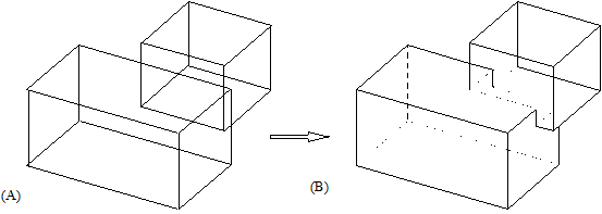
Union
(A) 2 solids
(B) 1 solid
Extruding 3D surfaces and surfaces of solids
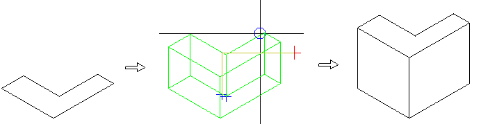
The ![]() Extrude tool provides additional support as you work in three dimensions: modeling solids can be precise or intuitive. You can turn any existing 3D surfaces into solids or draw any outlines on surfaces of solids and then model these outlines freely in three dimensions: the result is always a 3D solid.
Extrude tool provides additional support as you work in three dimensions: modeling solids can be precise or intuitive. You can turn any existing 3D surfaces into solids or draw any outlines on surfaces of solids and then model these outlines freely in three dimensions: the result is always a 3D solid.
Extrude along path
Using the ![]() Extrude Along Path tool, you create solids or surfaces by extruding an open or closed profile along a path.
Extrude Along Path tool, you create solids or surfaces by extruding an open or closed profile along a path.
You can even use a path that does not touch the profile. You can simply move the path to the profile. In addition, you can rotate the profile according to specific rules.
Rotate
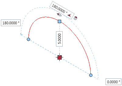
Donut-shaped solids are best created using the ![]() Rotate tool: A planar outline of any shape is revolved about an axis.
Rotate tool: A planar outline of any shape is revolved about an axis.
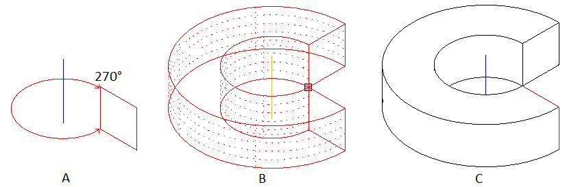
(A) Profile and axis (isometric view)
(B) Preview of solid (isometric view)
(C) Final solid (hidden line image)
Loft
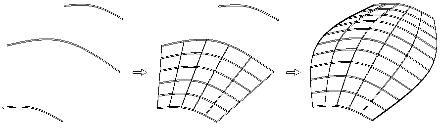
Using the ![]() Loft tool, you model solids or surfaces between two or more planar profiles. These profiles can be open or closed. It is not necessary that the profiles have the same number of points or corners. Lines connecting the profiles are not required either.
Loft tool, you model solids or surfaces between two or more planar profiles. These profiles can be open or closed. It is not necessary that the profiles have the same number of points or corners. Lines connecting the profiles are not required either.
Select the profiles one after the other. Allplan immediately displays a preview so that you can adjust the settings and thus control the final result.
Sweep path
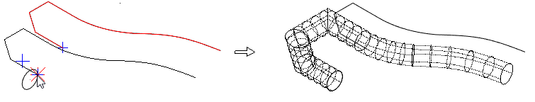
Using ![]() Sweep Path, you create 3D solids or 3D surfaces from at least two profiles that are joined along at least one path. It is not necessary that the profiles have the same number of points or corners.
Sweep Path, you create 3D solids or 3D surfaces from at least two profiles that are joined along at least one path. It is not necessary that the profiles have the same number of points or corners.
If ![]() Loft does not produce the solid you need, use
Loft does not produce the solid you need, use ![]() Sweep Path instead.
Sweep Path instead.
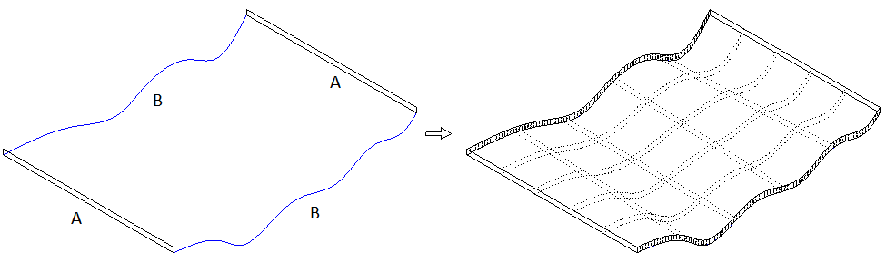
(A) Profiles
(B) Paths
Compatibility with other modules
You can convert three-dimensional data created in other modules of the Architecture family or in the Digital Terrain Model module to 3D elements and solids at any time.
If, for example, you want to use general 3D elements with curves in the architectural modules and convert them to planes, you first have to convert the 3D elements to polygonal solids or surfaces using ![]() Convert Elements - General 3D element to 3D solid, 3D surface.
Convert Elements - General 3D element to 3D solid, 3D surface.
Animation
With the help of the presentation modules and of the Animation module in particular, you can give your 3D solids and ‑surfaces a realistic look:
Every solid can be assigned material textures and surface properties; animated movies of urban planning models or high-resolution rendered images of modeled details including transparency, reflection, luster and shadows are possible at any time.
Data from the modules in the Architecture family
Prior to using the Animation module to visualize a large building that you have created with the architecture modules, you can convert a copy of the building model to 3D in order to save data. The architectural elements will lose some of their "intelligent" properties in the process, but the volume of data will be smaller.
Compatibility with modules in the Architecture family
Compatibility with the modules in the Architecture family is ensured at all times:
Note: If, for example, you want to use general 3D elements with curves in the architectural modules and convert them to custom planes, you first have to convert the 3D elements to polygonal solids or surfaces using ![]() Convert Elements - General 3D element to 3D solid, 3D surface.
Convert Elements - General 3D element to 3D solid, 3D surface.
Compatibility with modules in the Engineering family
With the 3D Modeling module you can create a 3D general arrangement drawing that does not have any architectural components like columns, beams and walls. A 3D general arrangement drawing facilitates the process of applying reinforcement in "Reinforce with Model" mode.
| (C) Allplan GmbH | Privacy policy |
