![]() Wall design parameters of reinforcement and fixtures
Wall design parameters of reinforcement and fixtures
The settings you define here are the same as those you can find in the ![]() Configurations and in the reinforcement type catalog (provided you use the
Configurations and in the reinforcement type catalog (provided you use the ![]() Design tool for walls).
Design tool for walls).
Lattice girder height
You can specify how the lattice girder height is calculated. In addition to the Manual selection option, which you can use to specify a lattice girder directly in the palette, the program provides the three options: 1, 2 and 3.
Option 1: the girder height is calculated from the wall thickness minus the concrete covers and twice the value of the bar thickness entered. The tolerances specified are taken into account.
Using this option, you can control how the height is calculated, as the girder heights specified in the girder catalog often differ from the height between the bottom boom and the top boom.
Option 2: the girder height is calculated from the wall thickness minus the concrete covers and the actual diameters of the first cross bars. If the cross bars are not in the first layer, all the diameters of the outer bars are also considered. The tolerances specified are taken into account.
Option 3: the girder height is calculated from the wall thickness minus the value specified. The program adjusts the concrete cover so that the combination of possible spacers and calculated cross bars is as close as possible to the value specified. It is essential that the entire reinforcement is defined before it is created. Otherwise, the concrete cover cannot be calculated correctly. The tolerances specified are taken into account.
Note: The Bar thickness parameter for option 1 and the Value subtracted parameter for option 3, which are used to calculate the girder height, as well as the Spacers for option 3 are defined in the Lattice girders configuration entry.
Edge offset
Edge offset option
Option 1: the following edge offsets are preferred.
The edge offsets are ignored when
Option 2: the following edge offsets are always used even if the offset between the long leaf and the short leaf exceeds the offset to the girder edge and/or the maximum offset between the long leaf and the short leaf (value C).
Minimum edge offset of short leaf
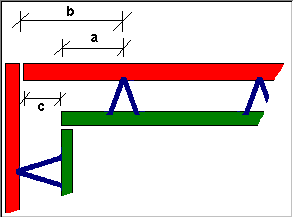
Limit value for the minimum offset between the panel edge and the shorter leaf (see illustration, A).
The program attempts to use the Edge offset specified in the palette. This value is measured from the longer leaf. Depending on the value that results in a larger offset to the shorter leaf, the program uses this parameter or the following one. The program always complies with this minimum offset so that there is enough space for corner reinforcement.
Minimum edge offset of long leaf
Limit value for the minimum offset between the panel edge and the longer leaf (see illustration, B).
The program attempts to use the Edge offset specified in the palette. This value is measured from the longer leaf. Depending on the value that results in a larger offset to the shorter leaf, the program uses this parameter or the following one. The program always complies with this minimum offset so that there is enough space for corner reinforcement.
Maximum offset between long leaf and short leaf
Maximum offset between the longer leaf and the shorter leaf (see illustration, C). If this value is exceeded and the Edge offset option is not set to 2, the edge offset of the lattice girder is taken from the palette.
Openings
Lattice girders from height / width
As soon as the values specified are exceeded, the program places lattice girders to the left and right of an opening. If an opening is smaller than this limit, it is ignored during girder distribution.
| (C) Allplan GmbH | Privacy policy |
