![]() Palette for Window SmartParts + Window SmartParts
Palette for Window SmartParts + Window SmartParts
You can assign an inner or outer window sill to the ![]() Window SmartPart.
Window SmartPart.
Notes: You can insert a Window sill SmartPart in a window opening if the bottom edge of the opening is horizontal.
If you assign an inner or outer window sill to a ![]() Window SmartPart, these elements are no longer treated as individual elements; They merge to form a single object. This has effects on analyses using
Window SmartPart, these elements are no longer treated as individual elements; They merge to form a single object. This has effects on analyses using ![]() Reports. Allplan treats Window SmartParts with inner or outer window sills as a whole, analyzing them as Windows. You cannot analyze these window sills as separate elements.
Reports. Allplan treats Window SmartParts with inner or outer window sills as a whole, analyzing them as Windows. You cannot analyze these window sills as separate elements.
If you want to analyze window sills separately, you must create them as separate Window sill SmartParts using the ![]() Window SmartPart tool. Select Window sill in the list box at the top of the palette. You can then analyze these separate Window sill SmartParts as individual elements using the
Window SmartPart tool. Select Window sill in the list box at the top of the palette. You can then analyze these separate Window sill SmartParts as individual elements using the ![]() Reports tool (Window sills.rdlc).
Reports tool (Window sills.rdlc).
Window sill tab
Outside / Inside
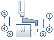
After having selected the Create window sill option, you can enter the dimensions (1-6) for the window sill.
You can see the dimensions in the graphics above.
Offset to the left / Offset to the right: you can define how far the window sill is from the window opening.
Note: The Height value (sum of height 1 + height 2 + offset) is for information. This value is an attribute of the window sill. The program uses it to calculate the height. Based on this height, you can decide to provide fall protection. Using ![]() Assign, Modify Object Attributes (shortcut menu of SmartPart), you can check the attributes of the SmartPart.
Assign, Modify Object Attributes (shortcut menu of SmartPart), you can check the attributes of the SmartPart.
Outside 2D representation / Inside 2D representation
Layer: select the layer on which you want to place the window sill of the SmartPart in 2D. The default setting for window sills is AR_WSILL.
Format from Layer: when you select this option, the settings for pen, line type and color are taken from the selected layer.
Pen / Line type / Color: when Format from Layer is not selected, you can choose the pen, line type and color.
Outside 3D representation / Inside 3D representation
Layer: select the layer on which you want to place the window sill of the SmartPart in 3D. The default setting for window sills is AR_WSILL.
Format from Layer: when you select this option, the settings for pen, line type and color are taken from the selected layer.
Pen / Line type / Color: when Format from Layer is not selected, you can choose the pen, line type and color.
Surface: click the button to select a surface file for the window sill in 3D (SURF file format, Allplan surface file). Click ![]() to switch off surfaces.
to switch off surfaces.
Surface elements
By selecting one of the check boxes, you can assign a Hatching style, a Pattern, a Fill or a Style area to the surfaces in 3D.
| (C) Allplan GmbH | Privacy policy |
