Create pattern line
 Module(s): Advanced Draft + Site Plan
You can use the  Create Pattern Line tool to resize a pattern line between individual lines, polylines, splines or composite elements. The pattern line’s pen and color are adopted from the element. You can also modify existing pattern lines.
To create a pattern line between two elements
- Click Create Pattern Line (How).
- Click New in the input options.
- Click the (composite) element or polyline (in the active file) which serves as the top of the slope.
- For composite elements, specify from which element and to which element the pattern line is to stretch. Click the right mouse button to select the entire composite element.
- Click the element at the base of the slope or enter a polyline that is to form the base of the slope.
When selecting this element, make sure that you do not click it near to an end point or a control point. In this case, the pattern line would be based on the point clicked and not on the element. You can easily tell whether you have selected the element: it is displayed in the selection color.
- Set the parameters of the pattern line.
Notes:
- Based on the top and base of the slope, Allplan automatically detects the direction of the pattern line.
- If you delete the base of the slope, the slope reverts to the original element. In this case, the pattern line is applied to the element.
- If you move the top or the base of the slope, the slope adapts automatically.
- If you want to display the element that represents the top of the slope, you must select the Show reference line parameter.
To modify existing slopes
- Click Create Pattern Line (How).
- Click Modify in the input options.
- Click the slope.
- Set the parameters of the pattern line.
Note: Click  Off to convert a pattern line back to the original element.
Combinations of parameters
Element
|
Intersection
|
Support slopes?
|
Pattern division?
|
Polyline
|
No
|
Yes
|
Only with slope
|
Polyline
|
Miter
|
No
|
No
|
Polyline
|
Joint
|
No
|
No
|
Polyline
|
Seamless
|
Yes
|
Yes
|
Line
|
Irrelevant
|
Yes
|
Only with slope
|
Other
|
Irrelevant
|
Yes
|
Yes
|
Examples (A= base of slope)
Position
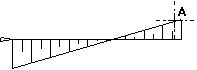
Left + mirrored (LM) or right + not mirrored (R)
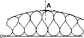
Left + mirrored (LM)
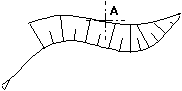
Left + mirrored (LM) or right + not mirrored (R) or centered + mirrored (CM)
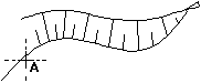
Centered + not mirrored (C) or left + not mirrored (L)
Troubleshooting
- The hatching is not visible on the screen:
Inadequate slope base —› replace it - Slope intersection does not work cleanly:
Increase the pattern division value.
Check whether you have set a suitable pattern width. - When I zoom, the hatching is not drawn in full:
Change the slope, increase the pattern height (the width will change automatically). Then reset the width of the pattern to its previous value. - In addition to the slope, normal pattern lines appear on the opposite side:
This indicates that there are several intersections and that Allplan uses only one of them for the slope.

