![]()
![]()
|
|
|
![]() Precast family
Precast family
The ![]() Formwork module provides comfortable tools for applying formwork to any concrete object modeled in Allplan.
Formwork module provides comfortable tools for applying formwork to any concrete object modeled in Allplan.
You can use all the tools provided by Allplan (architecture modules, 3D modeling, solid component ...) to model concrete objects.
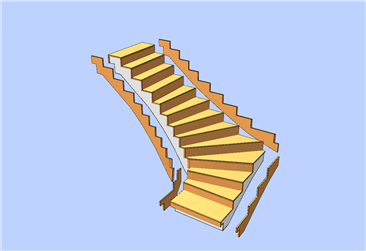
To model the bottom and top parts of architectural stairs (created with the ![]() Stairs module) in a way that is typical of precast elements, you can use the
Stairs module) in a way that is typical of precast elements, you can use the ![]() Structural Precast Element tool in the Structural Precast Elements module. When you have selected the Stair subtype in conjunction with the Architectural component input type, all you need to do is specify the bottom and top steps, set parameters and click the stair, which is then modeled immediately.
Structural Precast Element tool in the Structural Precast Elements module. When you have selected the Stair subtype in conjunction with the Architectural component input type, all you need to do is specify the bottom and top steps, set parameters and click the stair, which is then modeled immediately.
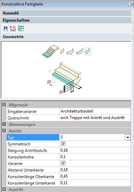
If available, you can also use this tool to create structural precast elements by defining parameters. Note, however, that modifying precast elements of this type deletes shuttering boards created beforehand.
Tip: To access the ![]() Structural Precast Element and
Structural Precast Element and ![]() Explode Structural Precast Element tools straight from the
Explode Structural Precast Element tools straight from the ![]() Formwork module, you need to select the
Formwork module, you need to select the ![]() Formwork module, show the Create and Change toolbars, select Customize on the Tools menu, open the Customize tab and select the Create or Change category and the Structural Precast Elements module and drag the icons of these two tools to the corresponding toolbars. Now you can also select these tools in the Tools palette.
Formwork module, show the Create and Change toolbars, select Customize on the Tools menu, open the Customize tab and select the Create or Change category and the Structural Precast Elements module and drag the icons of these two tools to the corresponding toolbars. Now you can also select these tools in the Tools palette.
After you have entered the concrete object, the program (![]() Create Formwork Areas and
Create Formwork Areas and ![]() Apply to Formwork Area tools) will continue and apply formwork to the concrete object fully automatically. As an alternative to this automatic feature, you can manually create formwork for the individual areas, too.
Apply to Formwork Area tools) will continue and apply formwork to the concrete object fully automatically. As an alternative to this automatic feature, you can manually create formwork for the individual areas, too.
This process is based on general, configurable rules, which help you control it. For example, you can make settings for joints or fixtures (nailers).
In addition, you can use the ![]() Create Shuttering Board Manually tool to create formwork elements which are not directly on a formwork area (e.g. supports, bracing) and make these elements intersect other shuttering boards using
Create Shuttering Board Manually tool to create formwork elements which are not directly on a formwork area (e.g. supports, bracing) and make these elements intersect other shuttering boards using ![]() Intersect Manual Shuttering Boards.
Intersect Manual Shuttering Boards.
After the formwork elements have been generated, you can edit individual elements. These elements are edited in the same way as wall and slab elements in the ![]() Edit Element tool. You can use the following tools:
Edit Element tool. You can use the following tools: ![]() Shorten / Lengthen Shuttering Board,
Shorten / Lengthen Shuttering Board, ![]() Split Up Shuttering Board,
Split Up Shuttering Board, ![]() Join Shuttering Board,
Join Shuttering Board, ![]() Model Shuttering Board (similar to
Model Shuttering Board (similar to ![]() Model Precast Elements) and
Model Precast Elements) and ![]() Delete Shuttering Board.
Delete Shuttering Board.
Additional tools are available for creating nailers manually (![]() Place Nailer), modifying and deleting nailers (
Place Nailer), modifying and deleting nailers (![]() Modify Nailer and
Modify Nailer and ![]() Delete Nailer) and modifying joints (
Delete Nailer) and modifying joints (![]() Modify Joint).
Modify Joint).
When you edit individual formwork elements, the program checks all the changes you make to ensure that formwork and concrete object are identical.
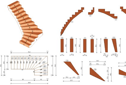
You can create an exploded view for verification purposes (![]() Create Exploded View tool).
Create Exploded View tool).
Finally, you can generate production data to be sent to the machine (![]() Create Production Data) as well as generate a key plan (
Create Production Data) as well as generate a key plan (![]() Create Associative View for Shuttering Board) and lists/schedules (
Create Associative View for Shuttering Board) and lists/schedules (![]() Lists/Schedules). The results are transferred directly to the relevant machine without any information being lost.
Lists/Schedules). The results are transferred directly to the relevant machine without any information being lost.
| (C) Allplan GmbH | Privacy policy |
