![]() Tool(s): Wall + Downstand Beam, Upstand Beam + Upstand + Strip Foundation
Tool(s): Wall + Downstand Beam, Upstand Beam + Upstand + Strip Foundation
You can use ![]() Curved Component to draw curved components (walls). The circle is approximated by a polyline: as a result, Allplan creates short, straight segments of linear components, which you can address as a single entity. You can set the number of segments in a curved component.
Curved Component to draw curved components (walls). The circle is approximated by a polyline: as a result, Allplan creates short, straight segments of linear components, which you can address as a single entity. You can set the number of segments in a curved component.
Note: Quantities are calculated based on the segments.
Schematic overview of curved and polygonal walls
To create a curved component
The secant is displayed.
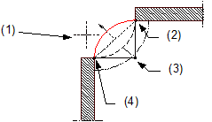
(1) Direction in which the arc is to extend – relative to the secant
(2) Connecting point = end point of linear component
(3) Center point
(4) Connecting point = start point of linear component
The position of the component axis and its direction of extension are displayed in the preview. In the case of components with multiple construction layers (e.g. walls), you can see the component setup and the thickness of the various layers. The position of the fist layer is identified by the number 1, which is displayed in the color associated with the component axis.
You can change this setting at any time while entering components.
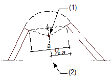
(1) Center of circle
(2) Perpendicular bisector
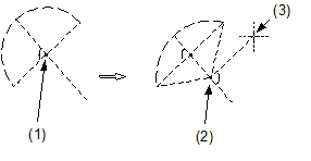
(1) Proposed center of circle
(2) New center of circle
(3) Crosshairs
The curved component is drawn.
Note: When you use ![]() Stretch Entities to modify curved components (at wall junctions, for example) while the component axis is hidden, the modifications you make do not affect the axis. This can cause numerical inaccuracies when you dimension the curved component. When you use
Stretch Entities to modify curved components (at wall junctions, for example) while the component axis is hidden, the modifications you make do not affect the axis. This can cause numerical inaccuracies when you dimension the curved component. When you use ![]() Stretch Entities while the component axis is switched on, curved components behave like circles; i.e. the component is moved.
Stretch Entities while the component axis is switched on, curved components behave like circles; i.e. the component is moved.
| (C) Allplan GmbH | Privacy policy |

