![]()
![]()
|
|
|
The tool Haunch was especially developed for intersecting haunches between precast girders and cast in situ concrete decks, considering changing distances due to different geometries of their axes. However, this functionality can analogously be used for similar application cases.
This tool allows for geometrically intersecting structural members of the type girder or link girder with structural members of the type deck (“union”).
In doing so, the cross section assigned to the girder must contain at least one boundary with an assigned structural unit (which forms the structural member) and one boundary without assigned structural unit which is used for the intersection with the cross section of the deck.
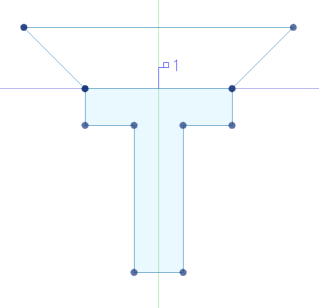
Fig. 1: Cross section of the structural member “girder” with a boundary without structural unit for the intersection
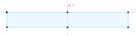
Fig. 2: Cross section of the structural member “deck”
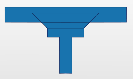
Fig. 3: Intersection of the boundary (without structural unit) of the girder with the boundary of the deck
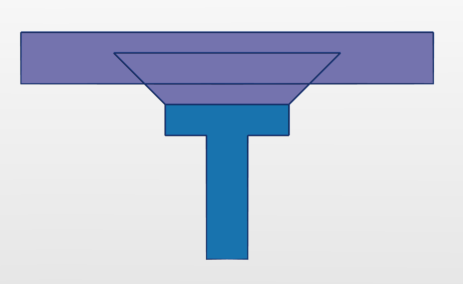
Fig. 4: The remaining area of the intersected boundary is merged with the boundary of the deck into one area
Here it should be noted that the boundary of the girder to be intersected always lies within the boundary of the deck (in particular if the distance between the girder and the deck changes along their axes) - if applicable, this can be managed by varying the height of the boundary using variables.
Within the Boolean operations, the deck is called left operand, the girder or link girder foreign operand.
To define an intersection of a girder with a plate
Note: During the input of the steps 3 and 4, it is possible to define the range along the axis of the two structural members within which the intersection should be performed by interactively defining the respective start and end stations. In doing so, you can also select not yet existing stations which then are automatically created. For this, use the corresponding checkboxes in the Property window. By default (if the checkboxes are unticked), the intersection is performed from the first to the last station.
The respective definitions of the Boolean operations are saved in the structural members of the decks in the submenu Booleans in the navigation tree and can be edited there.
|
(C) ALLPLAN GmbH |
Privacy policy |
