![]() Tools: Create View + Create Section + Modify View and Section Properties
Tools: Create View + Create Section + Modify View and Section Properties
In this dialog box, you can define how to calculate hidden-line images.
Note: The settings in the Hidden Line Image in Destination Document palette and in the Settings for Hidden-Line Images dialog box of the associative views are mutually dependent.
Tip: The Preview area shows the effects of the settings.
Surface elements
No surface elements!
With this setting, surface elements are not visible in hidden-line images.
Only fills from colors
With this setting, fills represent surface elements in hidden-line images. The element color defines the fill color or, if a surface is assigned, the color of the surface file. Textures will be ignored.
Create bitmaps from textures, fills from colors
With this setting, surface elements with textures appear as bitmap areas in hidden-line images. Areas that are not assigned a texture are shown with a fill, the color results from the element color or the color of the surface file.
Note: Bitmap areas will correctly be resized (cropped) in parallel projections only (elevation and isometric views). But you can also achieve realistic images in perspectives with granular surfaces such as sand or plaster.
Use Consider transparency to display surfaces to which you have assigned transparent surfaces as transparent so that hidden surfaces become visible.
Click the Surfaces... button to open the Set Surfaces palette, where you can assign different colors to element colors. Allplan will then display the new colors - instead of the element colors - in the hidden-line image.
Consider light
When you select the Consider light setting, the program calculates lights in hidden-line images in accordance with the settings for Light angle in view and Light angle to visible axis. This is not a sun study; the program idealizes the light situation!
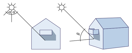
Use Light angle in view (left / right) to define the direction of the shadows.
Use Light angle to visible axis (length of shadow) to define how long the shadows are.
|
|
|
alpha: light angle in view, -180° (left) to 180° (right) |
Use Light intensity to specify how many shades of color are used for fills and bitmaps. Enter a value between 1 and 100. The smaller the value, the darker the image.
Use Fill-in light intensity to brighten up shadows and fills. Enter a value between 0 and 100. When you specify an intensity of 0, the fill-in light will not be calculated.
Select Show shadows if you want to display shadows. If you enter negative values for Light angle in view (left / right), the shadows are cast to the left. If you enter positive values, they are cast to the right. The smaller the value, the steeper the shadows. Use Light angle to visible axis (length of shadow) to control how long the shadows are in isometric views. The greater the value, the longer the shadows.
Adjacent edges
You can specify an angle up to which the program is to merge surfaces to make curves appear smoother. A great angle causes curves to appear as a silhouette.
|
|
|
|
|
Off |
Angle |
Angle |
Adjacent edges for architectural components
You can specify how adjacent edges of architectural components look. This setting is only available if Remove adjacent edges is selected. Otherwise, both options are active by default.
When Display adjacent edges between different surface elements or Display adjacent edges when material changes is selected, the program displays adjacent edges when a component has different surface elements (hatching style, pattern, fill) or materials.
Note: You can decide whether you want to use surface elements or materials. To do this, open the ![]() Options on the Components and architecture page and select the setting you want to use in the Components area.
Options on the Components and architecture page and select the setting you want to use in the Components area.
When Display adjacent edges for round components is selected, the program displays adjacent edges in round components (wall, column, chimney). This option is usually not selected.
Special settings
For architectural sections
This setting is not available with associative views.
Result
Display visible edges
When you select the Display visible edges check box, you can see all visible edges. The program uses the format properties you define here.
When you select the ![]() Pen,
Pen, ![]() Line,
Line, ![]() Color or
Color or ![]() Layer check box, the elements get the format properties defined in this dialog box. Otherwise, the elements retain the format properties with which they were drawn.
Layer check box, the elements get the format properties defined in this dialog box. Otherwise, the elements retain the format properties with which they were drawn.
Display hidden edges
When you select the Display hidden edges check box, Allplan also displays hidden edges. The program uses the format properties you define here.
When you select the ![]() Pen,
Pen, ![]() Line,
Line, ![]() Color or
Color or ![]() Layer check box, the elements get the format properties defined in this dialog box. Otherwise, the elements retain the format properties with which they were drawn.
Layer check box, the elements get the format properties defined in this dialog box. Otherwise, the elements retain the format properties with which they were drawn.
buttons in the border of the dialog box
![]() Load favorite,
Load favorite, ![]() Save as a favorite
Save as a favorite
![]() Reset
Reset
You can use this tool to reset all the entries in the dialog box back to their defaults.
|
(C) ALLPLAN GmbH |
Privacy policy |