![]() Configuration Attached reinforcement
Configuration Attached reinforcement
![]() "0° bars 1" tab
"0° bars 1" tab
Use grid:
Specify whether a grid should be used for the 0° bars or not. Whether the setting has to be selected or not is something that can always be found directly in the machine description. Generally, this option is selected on all machines for the 0° bars.
Note: If a grid is not specified then the program uses an internal grid of 10.0 mm to calculate the possible meshes for basic reinforcement so that the computing time is reduced!
The following options on this tab for the 0° bars are only evaluated if the Use grid option has been selected.
Grid offset:
If the Use grid option is selected then the grid spacing is entered here. The value is derived from the machine description provided by the manufacturer.
Separate grid for bars in 2nd layer:
Many machines can, if the 0° bars in the 2nd layer (what is meant here is the height of the bars during production of the meshes) have to be welded (i.e. the 0° bars are above the 90° bars), not weld the same grade as in the case where the 0° bars in the 1st layer are below the 90° bars. If this is the case then this option can be selected here.
The machine description states if this option has to be selected. Selection is not generally required.
Note: If use of a separate grid is selected for the 2nd layer, then creation of MWS reinforcement based on reinforcement type (with a slab created via ![]() Design and a wall also created via
Design and a wall also created via ![]() Design ) or Reinforcement percentage required and Reinforcement type (wall created via
Design ) or Reinforcement percentage required and Reinforcement type (wall created via ![]() Design (iWall)) is not selected as there would be no appropriate meshes!
Design (iWall)) is not selected as there would be no appropriate meshes!
Note: If use of a separate grid is selected for the 2nd layer then it is absolutely necessary to define the installation location and correct production position for longitudinal bars in the Basic slab reinforcement and Basic wall reinforcement titles on the Reinforcement layer tab in the attached reinforcement options. For walls created via ![]() Design (iWall), the correct settings must be defined in
Design (iWall), the correct settings must be defined in ![]() Basic reinforcement, … on the Basic reinforcement tab in the Parameters for attached reinforcement sub-dialog. Otherwise, for example, different grids would arise on the visible and invisible sides of a wall.
Basic reinforcement, … on the Basic reinforcement tab in the Parameters for attached reinforcement sub-dialog. Otherwise, for example, different grids would arise on the visible and invisible sides of a wall.
Grid offset:
If the Separate grid for bars in 2nd layer option is selected then the grid spacing is entered here.
This value is also derived from the machine description if required.
Number of grid positions:
Defines the maximum possible number of 0° rods that have to be aligned. As a result, it also defines the maximum possible number of welding points.
The value is derived from the machine description.
Number of grid positions per welding head:
The number of successive grid positions (usually 2 or 1) is defined for which a welding head is available in each case.
The value is derived from the machine description.
Max. number of bars per welding head:
Depending on the machinery, either all possible grid positions or just individual positions can be welded from the welding head.
The value is derived from the machine description if necessary.
If, for example, there are two grid positions below a welding head but only one must be welded (max. number of grid positions per welding head= 1), then not all possible grid positions of the 0° bars can be used and then there may be irregular bar spacings on the mesh.
When number of grid positions per welding head= 2) and max. number of bars per welding head = 1 then it makes no sense, as a start value for the offset for calculating the basic reinforcement mesh in the offsets tab for basic slab reinforcement or basic wall reinforcement or, later on, in the dialogs for defining the current bar spacings (e.g. with slabs in the offsets subdialog of the reinforcement parameter dialog in the Att. Reinf. B and also the Att. Reinf. T tabs if required), if the same value is set as for the grid!
Same grid positions for all reinforcement units:
Selection of this option means that the grid, in all reinforcement layers (or reinforcement units in the walls created by means of ![]() Design (iWall)) of a wall (e.g. double wall, visible reinforcement in leaf 2 and invisible reinforcement in leaf 1, or visible and invisible reinforcement on a concrete wall) or slab (e.g. lower and upper layer of reinforcement on a concrete slab), is used as a cover.
Design (iWall)) of a wall (e.g. double wall, visible reinforcement in leaf 2 and invisible reinforcement in leaf 1, or visible and invisible reinforcement on a concrete wall) or slab (e.g. lower and upper layer of reinforcement on a concrete slab), is used as a cover.
The setting for this value depends on your production method.
Note: So that the grid can be used as a cover in various reinforcement units, it is a condition that the use of a grid is selected for the corresponding direction! Otherwise, the program calculates the internal grid at 10.0 mm so that generally the impact of the option cannot be detected.
Note: Selecting the option only means that the grid positions are identical in all reinforcement units. It is not absolutely necessary that the selected spacings for the bars are identical! For example, specifying an as-value simply means that the chosen bar spacings of a reinforcement unit are a multiple of another reinforcement unit. If the bar spacings are also identical then further manual procedures are required during design or modification such as fixing the bar spacings.
![]() "0° bars 2" tab
"0° bars 2" tab
Min. length (straight bar, normal case):
The minimum permitted bar length is set here. The length entered always refers to a straight bar that is not bent. Shorter bars cannot be transported cleanly or aligned by the machine.
This value is derived from the machine description.
If, during creation of the mesh, there is a bar that is shorter than the size stated here due as recesses or inclined edges, then it is not created. It can therefore happen that the offset between other bars is too large and the mesh becomes non-producible as a result. In order to prevent such unapproved meshes, there is the Lengthen bars to min. length option (see below).
Note: It should always be checked whether the stated size is lower or the same as the minimum mesh length. Otherwise, error messages occur when creating the mesh.
Additional checking of min. length:
In this case you can select the optional additional check for the minimum bar length of 0° bars requested by the machinery manufacturer on some systems. To do this, choose any other option rather than No. The two variants Last bar in alignment and Bar as first intersection point are available for selection.
With Last bar in alignment you can specify a custom length for the last bar in alignment (bars that are placed in alignment in a line). In Min. length you can define the minimum permitted bar length for the last bar in alignment. The length entered always refers to a straight bar that is not bent. Shorter bars cannot be transported cleanly or aligned by the machine. This value is derived from the machine description if necessary.
With Bar as first intersection point you can set if the minimum length of the last bar in a row of aligned bars should also be checked for the 0° bars from which the first intersection point with the 90° bars should be checked.
Note: The potentially necessary additional bar extension when choosing the bar as first intersection point is then only evaluated for the on one side only option via Lengthen bars to min. length . In this case, the last bars are extended in the direction of the interior of the element! If no or no – loose bars as well as on both sides are selected then the option is not taken into account. The program then displays a message to this effect.
Note: Furthermore, the Bar as first intersection point is fundamentally based on the creation of assembly bars. This is why the check is stopped in the program if, in the Assembly bars title on the General tab for Create assembly bars, another option is set as 0° and 90° at that point. The bars are then only checked in accordance with the normal rules for minimum length, lengthened if necessary, then a message is issued! Extension of the bar up until the next assembly bar or welding in an additional assembly bar are omitted and the bars are then labeled as loose bars.
It must also be noted that the Bar as first intersection point option is generally only evaluated if use of the grid is deactivated for the 90° bars! If the Use grid option on the 90° bars 1 tab is selected then the calculation is only checked in accordance with the normal rules for minimum length, extended if necessary and a message is issued! Extension of the bar up until the next assembly bar or welding in an additional assembly bar are omitted and the bars are then labeled as loose bars.
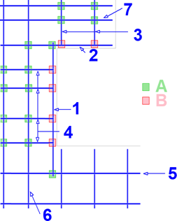
If the bar as first intersection point is not selected, the program performs the calculation without additional checks (P = production direction, A, E= start and end of mesh).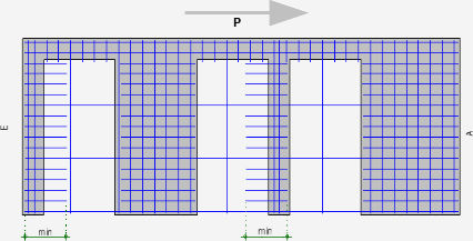
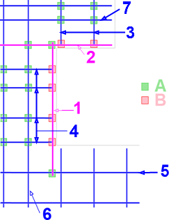
If bar as first intersection point is selected then the calculation described below is performed whilst taking the set Tolerance into account and, if required, an additional bar is welded in (P = production direction, A, E= start and end of mesh, Extra = additional 90° bar).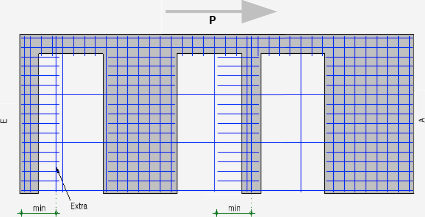
Tolerance:
The permitted tolerance for checking the bar as first intersection point is set here. This is then taken into account when checking the last bar in the production direction.
If the bar as first intersection point option is selected then the below process is followed for the bars which may have to be extended, depending on the location (first bar and a bar in the mesh interior as well as the last bar).
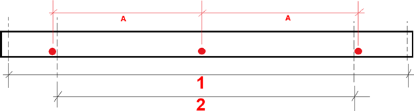
For bars at the start of the mesh and in the middle, the following rules apply:
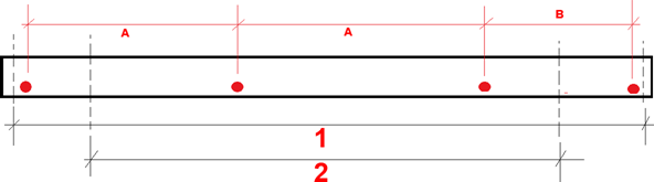
The following checks are carried out on bars at the end of the mesh:
Note: If, due to manipulation in the ![]() Mesh Welding System Editor (e.g. deleting a crossing 90° bar), one or both condition(s) for the bar length to be checked are no longer observed, then the corresponding bars become loose bars. They are then correspondingly labeled as loose bars and the undercutting of the required lengths is stated as a reason in the Properties in MSA Editor within the Cause(s) for loose bars tab as well as in the flyout for the bar. There is no automatic update of the calculation of length for the 0° bars that was described beforehand. The length of the reinforcement is recalculated only when the geometry of the element or the necessary as-value of the reinforcement unit is amended.
Mesh Welding System Editor (e.g. deleting a crossing 90° bar), one or both condition(s) for the bar length to be checked are no longer observed, then the corresponding bars become loose bars. They are then correspondingly labeled as loose bars and the undercutting of the required lengths is stated as a reason in the Properties in MSA Editor within the Cause(s) for loose bars tab as well as in the flyout for the bar. There is no automatic update of the calculation of length for the 0° bars that was described beforehand. The length of the reinforcement is recalculated only when the geometry of the element or the necessary as-value of the reinforcement unit is amended.
Max. length (straight bar):
The maximum bar length is defined here.
This value is derived from the machine description.
Note: It should always be checked if the stated dimensions are larger or identical to the maximum mesh length, otherwise error messages will appear upon creation of the mesh.
Max. number of bars in alignment:
If the number of bars in a Iine that are placed in alignment is restricted, then the corresponding number of permitted bars should be entered here. Bars lying in succession could, for example, arise due to recesses in the mesh.
This value should also be derived from the machine description.
Uniform diameter for bars in alignment:
With some machines, all bars in alignment must have the same diameter. If there is a corresponding definition in the specification from the machine manufacturer, then this option should be selected.
Note: The automated option for determining the basic reinforcement mesh always provides a solution where all bars are in alignment and have the same diameter. Only when secondary reinforcements are created, then secondary reinforcements are manually pushed into the grid or are screened, does the Uniform diameter for bars in alignment option become applicable
Lengthen bars to min. length:
This option can be used to control how the program handles bars that are shorter than the minimum permitted length. You can choose from four options: no, no - loose bars, on one side only and on both sides.
This value is also generally derived directly from the machine description if required.
Note: If bars are extended and they then overlap with other bars that have been extended or not, then they are "merged" together to make one single bar.
Note: It is expedient that one of the on one side only or on both sides is set by default to correct the length of the bars, even if correction to the machine is also possible, as impermissible meshes resulting from overly large bar spacings or bars with fewer than 2 welding points as a result of omitted, short bars may be avoided by doing so!
x-direction of mesh:
This setting is only important if one of the following conditions is satisfied:
Regarding the 0° bars, the minimum and maximum bar projections at the front and back are set for these parameters and they affect the min. length (last bar in alignment) ere.
Normally (such as the x-direction of the element ), the algorithm assumes that the first welded 90° bar is on the side closest to the local origin of the element. The local x-axis of the mesh then points in the same direction as the local x-axis of the element.
However, if the specifications from the product manufacturer contain data or information stating that production of the mesh takes place as the first welded 90° bar is on the side that is furthest away from the local origin of the element or that one of the above-stated conditions is satisfied, then it may be necessary, for the x-direction of the mesh, to set the Use opposite x-direction of element option.
Note: Further notes regarding the setting for these parameters also arise from the location of the mesh welding system with regard to the table on which the precast elements are produced. In most cases (at least with new factories), the mesh welding system is placed such that turning or rotation of the mesh is not required! Collaboration between the individual factory and the manufacturer of the mesh welding system should certainly take place.
Note: This option should only be set with the utmost caution, as later turns or mirroring of the element or turning of the mesh for production cannot be taken into account here. If required, the settings in the NC generator driver catalog must be amended!
Regarding the impact of the x-direction of the mesh parameter on the 90° bars, see below.
Note: The setting made here only has an internal impact. In MWS Editor the values are always displayed as if the mesh had the setting Use x-direction of element (x-values ascending from left to right). The mesh is only turned in the Editor if the span direction of an element changes, but not due to a change to the x-direction of the mesh!
Check minimum number of bars:
It is possible to select a check for the minimum number of 0° bars that are required for some systems.
Rule for checking:
The variant of the rule for the assessment is set out with the aid of this option:
Minimum number:
The number of 0° bars needed as a minimum is defined here. If the option is selected and the value is not complied with then an error message is issued by the program and the mesh is labeled as non-producible.
![]() "0° bars 3" tab
"0° bars 3" tab
Except for the Allow bending shapes at inclined edges parameter, the parameters set out here control the algorithm to find the basic reinforcement mesh.
Two bar diameters for basic mesh:
This option sets out if the program should search for just one diameter when searching for a mesh from the previous as-value (e.g. all 0° bars that are Ø6 or all 0° bars that are Ø8 or …) or if two adjacent bar diameters should be searched for (e.g. 0° bars as a combination of Ø6 and Ø8 or 0° bars as a combination of Ø8 and Ø10 or …).
It should be noted that generally only adjacent bar combinations are searched for to avoid issues during welding.
When selecting this option, the number of potential meshes in the "mesh pool" (see the Basic reinforcement tab of the General basic reinforcement configuration) and it is possible that a mesh is found that better satisfies the requirements. The setting depends on whether bars of differing diameters can be fed into the machine (there should be a statement to this effect in the machine description). Furthermore, it depends on whether you want to create meshes with different diameters as the cycle times per mesh may change as a result.
Note: Please note that adjacent bar combinations means two consecutive diameters listed in the diameter catalog here. No check takes place to see if the diameters really are consecutive (e.g. Ø6 / Ø8 or Ø8 / Ø10) in terms of size. If the diameters are not already arranged according to size in your diameter catalog then the corresponding combinations (e.g. Ø10 / Ø6 or Ø6 / Ø12) are also checked and used if required!
Irregular spacing for basic mesh:
This option is also merely available to increase the number of potential meshes in the "mesh pool" Basic reinforcement tab in the General basic reinforcement configuration). A statement to this effect will generally not be found in the machine description. The specification depends on if you want the clock times per mesh to change as a result of the irregular bar spacings.
If this option is selected, then a check always takes place on the intermediate bars if the available "regular" bar spacing is greater than double the minimum permitted spacing.
Allow bending shapes at inclined edges:
This is where it is defined if a bending shape should be created or not on an inclined edge (i.e. an edge below an angle of ≠ 90° relative to the direction of the bar), that is cut by a 0° bar. If restrictions are in place regarding bending shapes then there should be a statement to this effect in the machine description.
Note: The bending shapes that are defined for the edges in the input pallet of a wall created with ![]() Design (iWall) apply only to those edges that cover the single wall layer with the rectangle that has been outlined. Bending shapes on other edges can only be defined via
Design (iWall) apply only to those edges that cover the single wall layer with the rectangle that has been outlined. Bending shapes on other edges can only be defined via ![]() Bending shapes at any edge in
Bending shapes at any edge in ![]() Edit element or the
Edit element or the ![]() Element plan here!
Element plan here!
Note: No warning is issued if this option is deactivated and if bending shapes are set up but not created during design or modification on inclined supports or an inclined edge of the opening.
Use preferred spacing:
This parameter also controls the algorithm to find reinforcement. If this option is selected, then the algorithms for finding an ideal mesh are partially rendered ineffective as the number of potential meshes in the "mesh pool" (for information, see the Basic reinforcement tab in the General basic reinforcement configuration) is reduced somewhat. If there is a restriction on the part of the machine then something should be noted to this effect in the machine description. By specifying preferred spacings, the clock times per mesh may be changed if required.
Note: Simultaneous selection of the Use preferred spacing and Irregular spacing for basic mesh options means that the setting for irregular spacing will generally only become effective if no permissible mesh can be found for the defined, preferred bar spacings. A combination of various preferred spacings for an irregular combination does not take place!
Note: If the Use preferred spacing and Two bar diameters for basic mesh options are selected at the same time then during checking of a bar placement with two diameters, twice the value of a bar spacing is always set for bar spacing that has just been checked (e.g. preferred spacing = 20 cm ![]() Ø6/40 cm and Ø8/40 cm).
Ø6/40 cm and Ø8/40 cm).
Preferred spacing:
The desired values for the preferred spacings are entered in descending order here. Individual values are separated with a semicolon ";". If required, these specifications should be noted in the machine description.
Note: What must be borne in mind is that the bar spacings here, regardless of the unit set in ALLPLAN, must always be entered in [m] here!
If no permissible mesh can be found for the first preferred spacing then the next preferred spacing is used. If no permissible mesh can be found for any of the preferred spacings then a search is made for a suitable spacing and an error message is displayed. A warning is issued if values are entered here and the spaces in the reinforcement are fixed during design or modification so that the fixed values are not in line with the preferred values.
Create basic mesh of maximum width:
This option sets out if the program should also check meshes with a width that is as wide as possible when searching for meshes. When selecting the option, the number of potential meshes in the "mesh pool" (see the Basic reinforcement tab of the General basic reinforcement configuration) and it is possible that a mesh is found that better satisfies the requirements. The requirements of your factory determine if this option should be selected.
Note: If the found reinforcement should be as close to the requested as-value as possible, then this option should be deactivated! If the bars should be distributed evenly across the whole width of the element and the 0° bars should be as far outward as possible, then the option should be selected.
The algorithm initially determines the minimum and maximum placing widths for the 0° bars. Both of these widths are determined based on the default settings whilst taking the following conditions into account:
The maximum width (= 1 in the following image) that has been determined is then divided by the bar spacing A that has just been checked and the potential bar number N is calculated (N = rounded up(maximum width/A)). A check is then made to see if the combination of bar number N and offset A that was just found is greater than the minimum width ((N-1)*A ≥ minimum width [= 2 in the following figure]). If the condition is fulfilled then a potential distribution is found. This distribution that was found could then, if Create basic mesh of maximum width is deactivated, be arranged centrally whilst taking the rules for the grid into account or fixing the offset from the smooth edge on one side.
However, if the Create basic mesh of maximum width option is selected then the program attempts, if no fixing has been defined on the smooth edge, to move the placing width to the outermost possible point on one side and to extend the distribution width such that it matches the maximum width (=1 in the following illustration) as far as possible by adding an additional bar with a spacing of B < A. However, B must be larger than the minimum permitted offset from the diameter catalog (see min. axis offset on the Welding1 tab for straight bars and min. axis offset for bent bars on the Welding2 tab for bent bars), as well as corresponding to grid spacing if use of a grid is defined.
![]() "90° bars 1" tab
"90° bars 1" tab
Use grid:
Usually, no grid is specified for the 90° bars. If a grid is required then the specifications for it can be found in the machine description.
Note: It may be expedient to specify a grid anyway as, for example, the computing time for calculating the potential meshes for basic reinforcement may be reduced. If a grid is not specified, the program carries out calculations with an internal grid of 10.0 mm!
Note: If the Same grid positions for all reinforcement units option is activated for the 90° bars then a grid is also required, as is the case with the 0° bars, as the program would otherwise use the internal grid to calculate so that the impact of the option would not generally be visible.
The following options on this tab for the 90° bars are only evaluated if the Use grid option has been selected.
Grid offset:
If the Use grid option is selected then the grid spacing is entered here. The value is derived from the machine description.
Separate grid for bars in 2nd layer:
See the Separate grid for bars in 2nd layer settings on the 0° rods 1 tab. The value should be derived from the machine description. Selection of this option is not generally required.
Grid offset:
If the Separate grid for bars in 2nd layer option is selected then the grid spacing is entered here. This value should then also be derived from the machine description.
Number of grid positions:
If required, this value should be derived from the machine description. If a grid should be specified then it should be noted that grid spacing x number of grid positions results in a length that is greater or equal to the maximum mesh length (see Mesh 1 tab in the General basic reinforcement configuration) as otherwise error messages may readily arise due to, amongst other things, excessively large bar projections.
Same grid positions for all reinforcement units:
See the Same grid positions for all reinforcement units settings on the 0° bars 1 tab.
![]() "90° bars 2" tab
"90° bars 2" tab
Min. length (straight bar, normal case):
See the Min. length (straight bar, normal case) settings on the 0° bars 2 tab. This value is derived from the machine description.
Note: It should always be checked whether the stated size is lower or the same as the minimum mesh width. Otherwise, error messages occur when creating the mesh.
If the following option Additional check for bar groups is selected then the defined minimum length of an individual bar that is set out here also determines the minimum length of an individual bar within a bar group.
Additional check for bar groups:
Special rules are defined for successive 90° bars in some machine descriptions. If these are observed, then a bar can be combined with the previous and/or subsequent bar to create what are known as bar groups at this point. The minimum length applying to a bar in group is smaller than that for a 90° bar outside a group.
For bundling together into groups, the following rules apply:
Note: Only 90° bars that can be welded and fed in by the machine can be put together into groups. Bars that cannot be welded and are therefore labeled as "loose" (e.g. a 90° bar with just one welding point, manual reinforcement bars that cannot be screened by the user or the program (e.g. angle ≠ 0° or 90°] etc.) are not taken into account when summarizing for bar groups.
Note: The minimum approved mesh width is restricted if the additional check is selected for bar groups via the min. length (straight bar, normal case) criterion and not min. length (bar group) criterion here.
Min. length (bar group):
At this point, the minimum length for the summarized 90° bars of a bar group or an individual 90° bar that is not grouped with other bars can be determined. This value is also derived from the machine description.
Add 90° bars based on the x-direction of the mesh:
For the summarizing into bar groups, the production direction of the mesh (see the above parameter x-direction of the mesh) must be known. In addition, it is necessary to define from which side the 90° bars are supplied so that a clear summary is possible for several 90° bars that are in alignment.
The 90° bars are fed in either from the left or from the right here. The specification of direction, whether left or right is always based on the x-direction of the mesh.
Max. length (straight bar):
See the Max. length (straight bar) settings on the 0° bars 2 tab. This value is derived from the machine description.
Note: It should always be checked if the stated dimensions are larger or identical to the maximum mesh width, otherwise error messages will appear upon creation of the mesh.
Max. number of bars in alignment:
See the Max. number of bars in alignment settings on the 0° bars 2 tab. This value is derived from the machine description.
Uniform diameter for bars in alignment:
See the Uniform diameter for bars in alignment settings on the 0° bars 2 tab. This value is derived from the machine description.
Lengthen bars to min. length:
This value is also generally derived directly from the machine description if required.
For 90° bars without an additional check for bar groups, see Lengthen bars to min. length on the 0° bars 2 tab. In the case of 90° bars with an additional check for bar groups, the following rules apply:
![]() "90° bars 3" tab
"90° bars 3" tab
Two bar diameters for basic mesh:
See the Two bar diameters for basic mesh settings on the 0° bars 3 tab.
Irregular spacing for basic mesh:
See the Irregular spacing for basic mesh settings on the 0° bars 3 tab.
Allow bending shapes at inclined edges:
See the allow bending shapes at inclined edges settings on the 0° bars 3 tab.
Use preferred spacing:
See the Use preferred spacing settings on the 0° bars 3 tab.
Preferred spacing:
See the preferred spacing settings on the 0° bars 3 tab.
Create basic mesh of maximum width:
See the Create basic mesh of maximum width settings on the 0° bars 3 tab.
Extend the bar over the whole width if the mesh is extended:
If a mesh is extended transversely to the production direction, i.e. new longitudinal bars are added, then the first cross bar in the wider part of the mesh was generally only extended to the point that it could be welded to the previously present longitudinal bars without selecting the setting. As a result, it was not possible to cleanly grasp and transport the mesh during transport as the gripper could only grab the mesh on one side.
Selection of Extend the bar over the whole width if the mesh is extended may prevent such awkward transportation of the mesh. The welded bar is then guided over the whole width of the mesh.
This value should be derived from the setting in the machine description.
The setting for Extend bar over the whole width with a widened mesh has the options no (default setting for compatibility reasons), in the production direction, against the production direction as well as in both directions. The last option in both directions is then expedient if the production direction of the mesh has not been established during drafting and the mesh is rotated in the factory during production if required.
Such extension of the cross bars across the entire width of the mesh takes place both at the end and/or the start of the mesh as well as extensions of the mesh internally.
If the cross bar cannot be extended, e.g. due to locked zones, then it remains a loose bar and is highlighted with the message The bar is too short for transport of the mesh during production . Manual intervention is required at this point.
![]() "Welding points" tab
"Welding points" tab
Particularly with regard to recesses where the reinforcement has been cut, or on inclined element edges, it is possible that when it comes to the bars that run perpendicularly to the edge in question (e.g. the 0° bars), the bar projection beyond the last bar is parallel to the edge in question (in this case, a 90° bar), is less than the minimum permitted bar projection.
It does not necessarily have to result in an error message as the intersection points between the bars can simply be considered to be invalid. An error message is only displayed when all, or practically all bars that cross a bar in the other direction do not comply with the minimum bar projection and therefore have fewer than two valid intersection points for the bar (= welding points) crossing them!
However, not all mesh welding systems check if the minimum bar projection is followed at an intersection point so that a valid welding point is possible. These systems then generally go to each intersection point of 2 bar axes and even if one bar axis just touches the other bar axis (bar projection = 0), the welding head is moved down and tries to create a weld at this point. As a result there are not just problems with the stability of the welding points, but it is also possible that the lower-lying bar is deformed, the higher bar is pushed downwards and then welded at a crooked angle.
So that such invalid intersection points are not just initially recognized by the machine, there are options available on the welding points tab.
All points where bar axes intersect must be valid welding points.
At this point, you select that the program should check all intersection points on bar axes to see if the point is a valid or invalid intersection point. If invalid intersection points are found then the bar becomes a "loose" bar that is crossed by bars with a bar projection that is too short.
Note: If selecting this option then the following option Shorten bars if welding point is invalid should always be selected as otherwise bars may be invalid and the whole mesh could become invalid as a consequence!
Shorten bars if welding point is invalid
As "loose" bars often mean that a mesh is no longer weldable as, for example, the maximum offset between two adjacent bars is no longer complied with, or because the bar projection of a bar crossing becomes too large, then this is where it can be selected that bars that do not comply with the minimum bar projection are shortened so that there is no intersection point between the bar axes.
The option is only evaluated if All points where bar axes intersect must be valid welding points is selected beforehand!
Shorten after axis by:
The dimensions for shortening behind the bar axis are specified here.
If a 0° bar has to be shortened to the minimum length set in min. length (straight bar, normal case) or, if necessary, min. length (last bar in alignment) (see the above tab 0° BARS 2) or a 90° bar has to be shortened to the minimum length set out in min. length (straight bar, normal case) (see above tab 90° BARS 2) then the bar in question is extended by the dimension beyond the axis of the crossing bar that is set out in the Shorten after axis by parameter.
If a bar still has a bar projection over the next crossing bar that is not permissible after shortening behind the bar axis of a crossing bar, then the program attempts to further shorten the bar above the next crossing bar. If no solution can also be found in this case, then the crossing bar becomes a "loose" bar with welding points that are not permissible.
Note: If the shortening value is 0.0 then the axes just about touch each other, which can also lead to problems. For this reason, the value entered should always be > 0.0! Furthermore, the value entered for shortening shouldn't be too high as this may also lead to a bar being excessively shortened and then the bar projection at the following intersection point becomes too short.
Note: Selection of the last-named option should always result in a check that the shortened bars are still sufficiently guided onto the support if necessary.
Bar position accurate to 1 mm:
This option has an effect on the position of the bars in a placement. This option is selected by default.
In particular, the new options means when creating the production data, that when creating the meshes
This is important in particular if the elements are passed on to production in Unitechnik format, as within the RODSTOCK block in the databases for the individual bars, the parameters ±88888 = x-coordinate placing in mm, ±99999 = y-coordinate offset in mm and ±00000 = division = distance of identical bars from each other in mm only allow for one transfer of values as integers in millimeters.
Setting a new option is irrelevant for transferring in PXML format as the transfer of values lower than one mm (e.g. 0.5 mm) is possible. However, the option is evaluated in the same manner as for Unitechnik. If necessary, amend the option here.
Note: Note that the Bar position accurate to to 1 mm option must be deactivated when working with imperial units (Anglo-American measurement system, e.g. [feet and inches])! On the other hand, total bar spacing rounded off to 1 mm is always issued, which is generally unusable. If, for example, loose bars with a grid spacing of 8" (= 203³ mm) are transferred to a MWS mesh and a grid is used for the 0° bar, and worked for the 90° bars with a deactivated grid, then
|
(C) ALLPLAN GmbH |
Privacy policy |