![]() Tools: Downstand Beam, Upstand Beam + Upstand + Strip Foundation
Tools: Downstand Beam, Upstand Beam + Upstand + Strip Foundation
You can use ![]() Curved Component to draw curved components (walls). The circle is approximated by a polyline: This results in short, straight segments of linear components, which you can address as a single entity. You can define the number of segments.
Curved Component to draw curved components (walls). The circle is approximated by a polyline: This results in short, straight segments of linear components, which you can address as a single entity. You can define the number of segments.
Note: Quantity takeoff of curved and circular components is based on the segments.
Schematic overview of curved components and polygonal components
To create a curved component
The secant appears.
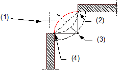
(1) Direction in which the arc is to extend – relative to the secant
(2) Connecting point = end point of linear component
(3) Center point
(4) Connecting point = starting point of linear component
The preview shows the direction of extension and the position of the component axis. In the case of multilayer components (for example, walls), you can see the layer structure with the thicknesses of the layers. The position of the first layer gets the number 1, which is the same color as the component axis.
You can change the direction of extension at any time, even while entering components.
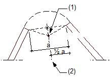
(1) Center of circle
(2) Perpendicular bisector
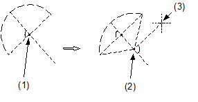
(1) Proposed center of circle
(2) New center of circle
(3) Crosshairs
ALLPLAN draws the curved component.
Note: When you use ![]() Stretch Entities to modify curved components (at wall junctions, for example) while the component axis is hidden, the modifications you make do not affect the axis. As the axis is no longer within the component, this might cause numeric inaccuracies when you dimension the radius of the curved component. When you use
Stretch Entities to modify curved components (at wall junctions, for example) while the component axis is hidden, the modifications you make do not affect the axis. As the axis is no longer within the component, this might cause numeric inaccuracies when you dimension the radius of the curved component. When you use ![]() Stretch Entities while the component axis is visible, curved components behave like circles; that is, the component will be moved.
Stretch Entities while the component axis is visible, curved components behave like circles; that is, the component will be moved.
|
(C) ALLPLAN GmbH |
Política de privacidad |