Note: Make use of the favorite files to make it easier to manage the definitions for the views, sections or isometric views. You can then save the current settings ![]() as a favorite. These favorites can then be loaded and edited with ease in the
as a favorite. These favorites can then be loaded and edited with ease in the ![]() Load favorite dialog box.
Load favorite dialog box.
![]() 'View - parallel projection' / 'View - isometric view' / 'Section' tabs
'View - parallel projection' / 'View - isometric view' / 'Section' tabs
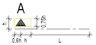
To help you define the direction in which the precast element is viewed, the program displays the selected element type as a rectangular slab panel, wall or box (structural precast element and precast element) in the graphic above the parameters. Depending on the selected element type, you can make different settings for the Principal directions. The actual viewing direction and rotation of the view or section and the required isometric setting are defined in the Projection area.
General
Name:
User-defined name that is visible in the tree structure of the layout catalog.
iTrigger
If no iTrigger is set, the corresponding sheet will always be created. In all other instances, the condition set for the respective precast element will be analyzed when creating the element plan. A decision will then be taken as to whether the corresponding view/section is to be created or not, based on the latest data for the precast element.
Please note the way the layout looks in the Layout Catalog will no longer correspond to the finished element plan if several lines are on top of each other or if individual cells are removed or created based on the specified conditions.
Note: If several cells are on top of each other in the same place (e.g. different views or sections for different conditions), you must select the respective cell that is the easiest option in the tree structure.
The final element plan may have fewer pages than there are in the Layout Catalog as a result of iTrigger. The actual pages generated are always displayed and numbered in the element plan window.
Note: Should the conditions for creating the latest element plan layout change later on, no more automatic adjustments will be made to the layout. The element plan must then be generated again, where required, using ![]() Create new element plan.
Create new element plan.
iTrigger
You can select one of the conditions defined under iTrigger in the General area.
Principal directions
Direction definition A:
Used for slab elements to define direction 6:
Used for walls created using ![]() Design (iWall) to define direction 1:
Design (iWall) to define direction 1:
No changes are possible for wall elements, structural precast elements and precast elements created using ![]() Design. For these elements, direction 1 is always the visible wall side or the viewing direction defined for a structural precast element or precast element.
Design. For these elements, direction 1 is always the visible wall side or the viewing direction defined for a structural precast element or precast element.
Direction definition B:
Specify the direction which is used for the orientation of the element in the element plan:
View
Viewing direction for view / section:
Specify the side from which you want to view the element in the view or section. You can also define the viewing direction by clicking in the isometric representation of the element in the graphic. You can do this without selecting the Viewing direction for view or Viewing direction for section line.
If a view or section is linked with another view or section by an anchor and the Align component option is selected, you can only define viewing directions that make sense.
In conjunction with isomeric views, the viewing direction is just a preselection of the principal direction. Use viewing direction for isometric view to define the final viewing direction of an isometric view.
Rotate view / section:
You can define the positions of the individual edges. The Rotate view or Rotate section line shows the edge on the right side. You can also define the direction in the graphic by clicking ![]() and
and ![]() . You can do this without selecting the Rotate view or Rotate section line.
. You can do this without selecting the Rotate view or Rotate section line.
If a view or section is linked with another view or section by an anchor and the Align component option is selected, you cannot rotate the view or section anymore.
Viewing direction for isometric view:
This parameter is only available on the View - isometric view tab. You can specify the actual direction of the isometric view by selecting the quadrant. The available settings match the standard views: I = "rear, right isometric view", II = "front, right isometric view", III = "front, left isometric view" and IV = "rear, left isometric view". The selected setting always applies to the direction selected for Viewing direction for view. The selected setting does not change even when you change the viewing direction for the view.
You can also define the isometric view by clicking it in the graphic at the top. You can do this without having to select the Viewing direction for isometric view line.
Rotate isometric view:
This parameter is only available on the View - isometric view tab. You can rotate the isometric view by +90° or -90°. Thus, you can display a rotated view of a column that is parallel to the longer edge of a sheet in landscape format or of a beam that is parallel to the longer edge of a sheet in portrait format.
Elevation
This area is only available on the View - isometric view tab.
x factor, y factor:
You can specify a zoom factor in the x-direction and y-direction. Thus, you can display isometric views at a scale that differs from that used for views or sections.
Section
This area is only available on the Section tab. Here you can either display a section through the entire element (1st clipping area) or define a 2nd clipping area analogous to the ![]() Create Section function.
Create Section function.
Viewing direction
x-direction, y-direction
x factor, y factor:
You can specify a zoom factor in the x-direction and y-direction. Thus, you can display sections at a scale that differs from that used for views.
Section identifier
This area is only available on the Section tab. The text featuring the section identifier defined here is always created centrally, either above or below the section object.
Name:
Any name of the section that is added to the section symbol and used for the section identifier generated automatically (section ... - ...).
Position:
You can specify here whether the automatically created section identifier should be created above (top) or below (bottom) of the section or not.
Offset:
You can use Define offset to define the vertical offset from the header or footer to the section.
Text attributes:
Enter or select attributes for the section identifier. Text height and width are entered into the current unit of length and the font angle is entered in [degrees]. You can also use Underline here to defined whether the section identifier is to be underlined on the element plan or not.
Display:
You can specify here whether the automatically created section identifier should be created or not. If you deactivate this option, you can, for example, select a label style as a section identifier.
Section object
This area is only available on the Section tab.
Auto-update:
When you select this option, the program updates the section object automatically to reflect changes you make to the geometry of the precast element. However, the program does not check whether the enlarged sections overlap other layout elements.
Limit section body by element:
If this option is selected then the section is restricted by the precast element in the section area.
If the option is not selected then the section is generally restricted only by the precast element.
![]() "Formwork/display" tab
"Formwork/display" tab
General
Formwork:
Specify for multilayer walls (double wall, thermal wall, and so on) and multilayer precast elements whether to display the Entire component or Individual layers of the component.
Display:
You can choose to display the view or section as a wireframe model (Wire) or hidden-line image (Hidden).
Stirrup shapes:
This setting is only available for front elevations of slabs or plan views, soffits or side elevations of walls (viewing directions 2 and 4 and viewing directions 3 and 5).
You can specify whether the placement is always visible in the view or section or only when the stirrup shape is not distorted.
In the latter case, the stirrup shape must not be sloping in relation to the views or sections. Otherwise, it is not visible in any view or section.
Show fixtures:
Whether fixtures are visible or not depends on the setting specified on the Element plan 1 tab of the fixture catalog. Here you can configure the program to display fixtures in accordance with the dimension line index or layer.
All: The dimension line index of the fixture or the layer has no effect on the scope of fixtures.
These only: Only the fixtures with dimension line indexes/layers are visible.
Note: Only the only these option via Layer makes the Print sets option available.
These excluded: All fixtures are / visible except those with the dimension line indexes/layers selected.
Visible only: This setting will only show the fixtures that are on the edges that are also visible in the view or the section. The fixture shown must protrude from the element or lie precisely on the corresponding edge/surface.
Dimension line index:
Select the dimension-line indexes you want to include or exclude. Click ![]() to open the Dimension line index dialog box, where you can
to open the Dimension line index dialog box, where you can ![]() add new indexes to or
add new indexes to or ![]() remove existing indexes.
remove existing indexes. ![]() and
and ![]() take you from entry to entry. You can see the dimension-line index assigned in the Index line.
take you from entry to entry. You can see the dimension-line index assigned in the Index line.
Note: Make use of the favorite files to make it easier to manage the definitions for the dimension line indexes. You can then save the current settings ![]() as a favorite. These favorites can then be loaded and edited with ease in the
as a favorite. These favorites can then be loaded and edited with ease in the ![]() Load favorite dialog box.
Load favorite dialog box.
Layers
Select the layers you want to include or exclude. Click ![]() to select a layer from the layers available in the dialog box. You can select predefined print sets from the Print set list box. Further information on using print sets can be found in Allplan Help.
to select a layer from the layers available in the dialog box. You can select predefined print sets from the Print set list box. Further information on using print sets can be found in Allplan Help.
Note: It is only possible to select print sets via the Not these option. This option is grayed out with all other options.
Show reinforcement:
The display of reinforcement depends on the setting in the Dimension string index, which can be defined by setting out the bar or mesh placements using the tools in the "Attributes" task area and also modify them. Here you can configure the program to display reinforcement in accordance with the dimension line index or layer.
All: The dimension line index of the reinforcement or the layer has no effect on the scope of fixtures.
These only: Only the bar or mesh placements with the set dimension line indexes/layer are visible.
These excluded: All bar or mesh placements are / visible except those with the dimension line indexes/layer selected.
Dimension line index:
Select the dimension-line indexes you want to include or exclude. Click ![]() to open the Dimension line index dialog box, where you can
to open the Dimension line index dialog box, where you can ![]() add new indexes to or
add new indexes to or ![]() remove existing indexes.
remove existing indexes. ![]() and
and ![]() take you from entry to entry. You can see the dimension-line index assigned in the Index line.
take you from entry to entry. You can see the dimension-line index assigned in the Index line.
Note: Make use of the favorite files to make it easier to manage the definitions for the dimension line indexes. You can then save the current settings ![]() as a favorite. These favorites can then be loaded and edited with ease in the
as a favorite. These favorites can then be loaded and edited with ease in the ![]() Load favorite dialog box.
Load favorite dialog box.
Layers
Select the layers you want to include or exclude. Click ![]() to select a layer from the layers available in the dialog box. You can select predefined print sets from the Print set list box. Further information on using print sets can be found in Allplan Help.
to select a layer from the layers available in the dialog box. You can select predefined print sets from the Print set list box. Further information on using print sets can be found in Allplan Help.
Note: It is only possible to select print sets via the Not these option. This option is grayed out with all other options.
Representation
Layer:
This setting is only available when you have selected Individual layers for the formwork in the General area. Use ![]() and
and ![]() to specify the relevant layer or click
to specify the relevant layer or click ![]() to open the table where you can define the display parameters for layers 1 to 6. Select the Display option to show the lines for selecting the elements that you want to display on the visible and invisible sides.
to open the table where you can define the display parameters for layers 1 to 6. Select the Display option to show the lines for selecting the elements that you want to display on the visible and invisible sides.
Note: Make use of the favorite files to make it easier to manage the layers for the dimension line indexes. You can then save the current settings ![]() as a favorite. These favorites can then be loaded and edited with ease in the
as a favorite. These favorites can then be loaded and edited with ease in the ![]() Load favorite dialog box.
Load favorite dialog box.
Display:
This setting is only available when you have selected Individual layers for the formwork in the General area. Specify whether the selected layer is visible in the view or section. Select this option to show the lines for selecting the elements that you want to display on the visible and invisible sides.
Reinforcement visible / invisible side
Specify how to display the reinforcement on the visible side or invisible side of the component or of the selected layer. You can choose between Do not display, Display and Display in detail.
When selecting Display in detail, you can see the additional Reinforcement to be displayed parameter. Click ![]() to open a dialog box in which you can define the reinforcement types you want to display. The possible reinforcement types match the visibility settings for reinforcement on the
to open a dialog box in which you can define the reinforcement types you want to display. The possible reinforcement types match the visibility settings for reinforcement on the ![]() Element Plan context toolbar.
Element Plan context toolbar.
Note: The program will only create these reinforcement types in the view or section. Consequently, you can only show or hide these reinforcement types by using the visibility settings. The visibility settings have no effect on other reinforcement types you did not define in the properties of the view or section.
By selecting this option, you can:
If you use the Display in detail option, turn on all visibility settings on the context toolbar before you start printing, ensuring that all reinforcement types are visible and in the printout.
Fixtures visible / invisible side
Whether fixtures are visible or not depends on the setting specified on the Element plan 1 tab of the fixture catalog. You can define the representation of fixtures in accordance with the dimension line index in the General area. Specify where you want to display the fixtures: on the visible or invisible side of the component or layer or on both sides.
Insulating boards:
Tiles (facing layers):
Define whether you want to display the elements for the component or for the selected layer.
Representation of surfaces
Surface on visible / invisible side
Specify where you want to display the surface: on the visible or invisible side of the component or on both sides. Only the boundaries of hidden surfaces are visible; surface elements are not visible.
Surface elements
Surface elements:
Set out the display of the surfaces on the elements here. This option is only available if you have gone to the General area, then Display to select the Hidden option.
No surface elements: Surface elements are not visible in hidden-line images.
Fills only: The program applies fills to the surfaces in hidden-line images. The fill color is derived from the element color or, if a surface is assigned, from the surface color of the precast element. Textures will be ignored.
Bitmap areas and fills: The program uses bitmaps to display surfaces with textures in hidden-line images. Surface elements without textures get fills (the fill color is derived from the element color or surface color).
Note: Bitmap areas will correctly be resized (cropped) in parallel projections only (elevation and isometric views). But you can also achieve realistic images in perspectives with granular surfaces such as sand or plaster.
Transparency:
When you select this option, surfaces to which you have assigned a transparent surface appear transparent so that hidden surfaces become visible.
Adjacent edges
Remove adjacent edges / max. angle of joint:
This option is only available if you have gone to the General area, then Display and selected the Hidden option.
When you select Remove adjacent edges this option, the program merges surfaces up to the Max. angle of jointyou specify to make curves appear smoother in hidden-line images. A great angle causes curves to appear as a silhouette.
|
|
|
|
|
Off |
Angle |
Angle |
visible edges
This area is only available if you have gone to the General area, then Display to select the Hidden option.
Display / Lock attributes / Attributes:
The other settings for Lock attributes and, if required, Attributes in this area and the subsequent Hidden edges area are only shown if you select the Display option. If the Display option is deactivated for a section, then only the front intersected area is shown, whereas with a view all the visible body (formwork) is hidden and only the reinforcement and/or fixtures are shown without the formwork.
If the Display option is selected then you can use Lock attributes to create the visible edges with the attributes set out here. Otherwise, the format properties of the precast element will be used.
Hidden edges
This area is only available if you have gone to the General area, then Display to select the Hidden option and the Display option has been selected below the visible edges.
Display / Attributes:
When you select the Display check box, hidden edges will be created with the attributes defined here. Otherwise, the program does not create any hidden edges.
Boundary lines
This area is only available for sections if you have gone to the General area, then Display to select the Hidden option.
Display:
When you select the Display check box, boundary lines will be applied to intersected component edges.
Projection / Attributes:
You can define the value by which the boundary lines project. Use the unit of length selected. In addition, you can define attributes for displaying these lines.
Thick line for border
This area is only available for sections if you have gone to the General area, then Display to select the Hidden option.
Display / Attributes:
When you select the Display check box, intersected edges will be created with the attributes defined here. Otherwise, the format properties of the precast element will be used.
Section display
This area is only available for sections if you have gone to the General area, then Display to select the Wire option.
Display section surface elements of architectural components:
This option is used to display the intersected areas of architectural components and 3D objects with their surface element assigned upon generation of the element plan with or without their surface elements.
![]() 'Clipping path' tab
'Clipping path' tab
This tab is not available for isometric views.
Clipping path
Display:
When you select the Display option, the selected clipping paths of the sections generated automatically are visible in this view or section. Clipping paths that are not selected are not shown. The name of a section stated under Name will always be displayed.
Note: All sections are available when you choose a view. When you select a section
Clipping line
Continuous / Length of line segments:
When you select the Continuous check box, the clipping line is a continuous line. Otherwise, the program creates line segments of the length specified that are attached to the min-max box of the direction symbol. Enter the lengths in the currently selected unit of length.
Attributes:
Here you define the attributes for displaying the clipping line.
Direction symbol
Place / Direction symbol:
When you select the Place check box, the clipping line gets the selected direction symbol.
Symbol size:
This is where you define the size of the direction symbol. When you enter 0, the size of the direction symbol will be defined automatically.
The direction symbol will be created within a min-max box whose height matches the defined size and whose width is 1.6 times this height. If you enter 0 for the size, the text height of the label defines the height of the min-max box.
The height of the actual symbol is three-quarters of the height of the min-max box. The distance between the tip of the symbol and the inner edge of the min-max box is the same as the height.
L = length of line segments
Note: The length of the line segments starts at the min-max box of the direction symbol.
Label
Text attributes:
Enter or select attributes for the section identifier applied to the section symbol. Text height and width are entered into the current unit of length and the font angle is entered in [degrees].
You can specify the name of the relevant section in the Section identifier area of the Section tab.
![]() 'Text' tab
'Text' tab
This tab is only available for views in parallel projection and for sections.
The areas of this tab are only available for views when the viewing direction on the View - parallel projection tab is defined in or opposite the direction of Direction definition A. This applies at all times to the Mark number of reinforcement, Mark number of fixtures, Opening, recess number and Element number areas for structural precast elements. The same applies with the exception of the Hollow blocks area for slabs.
When it comes to sections, the Mark number of reinforcement and Mark number of fixtures areas are always available. The Mark number of insulating boards area, on the other hand, is only available when the viewing direction on the Section tab is defined in or opposite the direction of Direction definition A.
Note: Text height and width are entered into the current unit of length and the font angle is entered in [degrees].
Element number
This area is only available for views.
Label / Representation / Text attributes:
Use this to specify the position, representation and attributes of the label.
No: No element number is output.
Lower left as placed: The panel number is in the lower-left corner. In the slab program, this defines the position in the placing drawing; in the wall program this defines the visible side of the elements.
Note: As slab panels are rotated in element plans, the number is usually not in the lower-left corner. However, the panels are always placed correctly as they are identified by the positions of their element numbers.
Centrally in the panel: The element number is in the middle of the element.
If the label for a view with viewing direction 1 or 6 is to be created, you can specify where the element number is displayed. Choose from the Only Number; Number, Oval; Number, Square; Number, Circle and Number, N-Corner settings.
Smart architectural symbols
This area is only available for views when you have selected a slab or wall as the element type for the element plan.
Label / Text attributes:
Use this to specify whether and how to label smart architectural symbols and define the attributes for the label.
Mark number of reinforcement
The program creates the mark numbers automatically, regardless of whether you choose to include dimensions or use the element plan table.
Basic reinforcing bars:
Specify whether you want to include the mark numbers assigned to the basic reinforcing bars. You cannot write the mark number on a (No) option, an All option or Just once for each mark number option.
Select Just once for each mark number and the program starts with the lowest mark number for the bar, then labels all remaining bars in ascending order. A bar is always labeled at the nearest possible mark. The labels appear in this case from top to bottom as well as from right to left.
Position:
Define whether the label should be directly on the reinforcement or in the opening or outside at this point. If selecting in the opening or outside then the bars are labeled within the openings or outside/to the right of the element. The labels in the openings are only made if the dimensions of the opening are larger or equal to the values set out in Min. lenght or width of opening here.
Secondary reinforcement:
Specify whether you want to include the mark numbers assigned to secondary reinforcement. You cannot write the mark number on a (No) option, an All option or Just once for each mark number option.
Position:
See Basic reinforcing bars
Labeling secondary reinforcements:
Here you can configure the program to label the secondary reinforcement in accordance with the dimension line index.
For the secondary reinforcement, you can also define the labeling depending on the setting of the attribute Dimension string index, which can be defined and amended for the placement of individual bars with the aid of the "Attribute" task area here.
All: The dimension-line index of the secondary reinforcement has no effect on fixture labels.
These only: Only the secondary reinforcement with the set dimension line indexes is visible.
These excluded: All secondary reinforcement is visible except those with the labeled dimension line indexes.
Dimension line index:
Select the dimension-line indexes you want to include or exclude. Click ![]() to open the Dimension line index dialog box, where you can
to open the Dimension line index dialog box, where you can ![]() add new indexes to or
add new indexes to or ![]() remove existing indexes.
remove existing indexes. ![]() and
and ![]() take you from entry to entry. You can see the dimension-line index assigned in the Index line.
take you from entry to entry. You can see the dimension-line index assigned in the Index line.
Note: Make use of the favorite files to make it easier to manage the definitions for the dimension line indexes. You can then save the current settings ![]() as a favorite. These favorites can then be loaded and edited with ease in the
as a favorite. These favorites can then be loaded and edited with ease in the ![]() Load favorite dialog box.
Load favorite dialog box.
Basic mesh reinforcement:
Specify whether you want to include the mark numbers assigned to the basic reinforcing meshes. You cannot write the mark number on a (No) option, an All option or Just once for each mark number option. The program creates the mark numbers automatically, regardless of whether you choose to include labels or use the element plan table.
The following input fields are only shown if, for at least one of the existing reinforcements, Basic reinforcing bars or Secondary reinforcement , Location has been selected for the In the opening or outside option.
Min. lenght or width of opening:
Define the dimensions from which the labeling should be within the opening. Labeling only takes place inside the opening if the openings are the same size or indeed larger than the dimensions that are set out here. All openings that are smaller are ignored and the bar is labeled on the element outline.
Offset to the element outline:
You can configure the program to define the length of the leader from the element outline to the mark number of the bar. This option is used if In the opening or outside is selected to define the minimum offset of the label relative to the element outline.
Offset:
You can configure the offset of the leader to the end point of the bar that should be used if he mark number is arranged outside the bar outline.
Text attributes:
Define the attributes for the labels.
Mark number of fixtures
Label:
To assign mark numbers to fixtures, use the Element plan 1 tab in the fixture catalog. Specify whether you want to include these mark numbers in the fixtures. The program creates the mark numbers automatically, regardless of whether you choose to use the element plan table.
Note: If a linear fixture or surface fixture is not completely within the section, the mark number of the fixture might not be right beside the fixture
To label fixtures:
Whether fixtures are labeled with a mark number or not depends on the setting specified on the Element plan 1 tab of the Fixture Catalog. Here you can configure the program to display mark numbers in accordance with the dimension line index or layer.
All: The dimension line index of the fixture or the layer has no effect on the scope of fixtures.
These only: Only the fixtures with dimension line indexes/layer are labeled with the mark number.
These excluded: All fixtures are shown with the mark number, except those with the dimension line indexes/layer selected.
Dimension line index:
Select the dimension-line indexes you want to include or exclude. Click ![]() to open the Dimension line index dialog box, where you can
to open the Dimension line index dialog box, where you can ![]() add new indexes to or
add new indexes to or ![]() remove existing indexes.
remove existing indexes. ![]() and
and ![]() take you from entry to entry. You can see the dimension-line index assigned in the Index line.
take you from entry to entry. You can see the dimension-line index assigned in the Index line.
Note: Make use of the favorite files to make it easier to manage the definitions for the dimension line indexes. You can then save the current settings ![]() as a favorite. These favorites can then be loaded and edited with ease in the
as a favorite. These favorites can then be loaded and edited with ease in the ![]() Load favorite dialog box.
Load favorite dialog box.
Layers
Select the layers you want to include or exclude. Click ![]() to select a layer from the layers available in the dialog box. You can select predefined print sets from the Print set list box. Further information on using print sets can be found in Allplan Help.
to select a layer from the layers available in the dialog box. You can select predefined print sets from the Print set list box. Further information on using print sets can be found in Allplan Help.
Note: It is only possible to select print sets via the Not these option. This option is grayed out with all other options.
Text attributes:
Define the attributes for the labeling here.
Text leader:
So that the mark number for labeling the fixture is shown away from the label, select the text leader option.
Text spacing :
Set the distance between the text for the mark number and the fixture here. The mark text is then shown away from the fixture, perpendicular to it, by the distance that is set.
Start symbol / End symbol:
Selection of the check box means you can then define if the leader should have a start symbol and/or an end symbol . The start is always on the mark text, the end is on the fixture.
Start symbol type / End symbol type:
If you have selected one of the check boxes, you can define the symbol type for the start of the line on the mark text and the end of the line on the fixture.
Height of start symbol / Height of end symbol:
You can define the height of the start symbol and/or end symbol here.
Mark number of insulating boards
This area is only available when you have selected a wall as the element type for the element plan.
Label / Text attributes:
Specify whether you want to use mark numbers to label insulating boards of thermal walls and sandwich walls created with ![]() Design (iWall). In addition, you can define the attributes for the labels. Starting at 1, the program numbers the boards of each precast element in ascending order. The program does not rearrange identical boards! You can transfer the mark numbers to production.
Design (iWall). In addition, you can define the attributes for the labels. Starting at 1, the program numbers the boards of each precast element in ascending order. The program does not rearrange identical boards! You can transfer the mark numbers to production.
Opening, recess number
This area is only available for views.
Label / Text attributes:
Specify whether you want to use automatic numbers to label openings or recesses (architectural openings, precast element) and define the attributes for the labels. If you create separate dimension lines for the openings and recesses, you can include these numbers in the dimension lines. As a result, you can see at once which dimension line belongs to which opening or recess.
For the viewing directions 1 and 6, the number of the recess appears in the middle of the opening and recess. For the viewing directions 2 and 4 and the viewing directions 3 and 5, the program places the numbers of the openings and recesses next to the opening or recess outside the precast element.
Edge attributes
This area is only available for views when you have selected a slab or wall as the element type for the element plan.
Bar projection / Length of inclined edges / Minimum length of edge:
Define whether you want to label all edges with the bar projection or whether you want to include the length in labels for inclined edges. Enter the minimum length in [m] above which inclined edges are labeled.
Unit / Text attributes:
Specify the unit and attributes for the labels.
Bars between lattice girders
This area is only available for views when you have selected a slab as the element type for the element plan.
Label / Text attributes:
As an alternative to longitudinal bars: You can output the number of the bars that are between two lattice girders. This is used with the defined attributes.
For example: 4xd12 means that there are 4 bars of diameter Ø 12 between these girders. If lattice girders are not defined, the program includes the entire longitudinal reinforcement.
Miters
This area is only available for views when you have selected the double wall as the element type for the element plan.
Label / Text attributes:
Use this to specify whether you want to label miters at double walls and define the attributes for the label.
Hollow blocks
This area is only available for views when you have selected the hollow core element or prestressed hollow core element as the element type for the element plan. In addition, this area is only available for a front elevation of a slab in span direction (viewing direction 2 or 4).
Numbering / Text attributes:
Specify whether you want to number hollow blocks of hollow core elements and prestressed hollow core elements and define the attributes for the label.
![]() 'Symbols' tab
'Symbols' tab
The majority of settings within this tab are only available for views in parallel projection. For the sections, you can only define the setting for the Center of gravity in drawing here
Symbols in drawing
Smooth edge / Basic edge / Bending shape:
This setting is only available for plan views or soffits (Smooth edge, viewing direction 1 or 6) or a front/rear view of walls (Basic edge, viewing direction 1 or 6).
Specify whether you want to display the symbol for smooth edges and the basic edges as well as the bending shapes at the supports.
The symbol used for the smooth edge on a slab element depends on the Symbol number defined on the Stop position/edges tab in the 'Labeling' configuration entry. When it comes to walls, the basic edge is always shown with a fixed triangle symbol whose size is predefined.
Recesses
This setting is only available for plan views or soffits of hollow core elements or prestressed hollow core elements (viewing directions 1 or 6) or structural precast elements.
Specify whether the program is to display recesses in the corresponding view in the element plan in the same way as in the placing drawing:
Diagonals for nonrectangular recesses are based on the same rules as for diagonals in placing drawings.
Note: There are no defaults for pen thickness and color. The program uses the current settings.
Recesses protruding over the panel edge (in other words, belonging to two or more panels) will be divided into parts of "notional" recesses in the relevant panels. These parts of "notional" recesses in different elements plans will then be marked in accordance with the rules mentioned. The same rules also apply to recesses near the edge of a panel. These recesses change the panel shape.
If Viewing direction for view = 6, the program replaces the representation of noncontinuous recesses at the top with that for noncontinuous recesses at the bottom because recesses that are at top in the placing drawing are at the bottom in the element plan and vice versa.
Note: In the case of slabs, automatic marking is only possible for "real" slab recesses created with the ![]() Recess, Opening in Slab tool in the Components task area or the
Recess, Opening in Slab tool in the Components task area or the ![]() Recesses tool in the Precast Slab task area. Recesses created with
Recesses tool in the Precast Slab task area. Recesses created with ![]() Model Precast Elements and recesses created at supports by automatic fixture features will not be marked automatically by the program in placing drawings and element plans. You must define marking together with the fixture or you must do this manually for recesses created with
Model Precast Elements and recesses created at supports by automatic fixture features will not be marked automatically by the program in placing drawings and element plans. You must define marking together with the fixture or you must do this manually for recesses created with ![]() Model Precast Elements.
Model Precast Elements.
In the case of structural precast elements, labels are only provided for recesses created using ![]() Model Precast Elements.
Model Precast Elements.
Formwork bottom symbol / File path:
This setting is only available for front elevations of slabs or plan views, soffits or side elevations of walls (viewing directions 2 and 4 and viewing directions 3 and 5).
Use File path to select a symbol you created at a scale of 1:1 in Allplan. The formwork bottom is marked with this symbol.
Symbols for formwork attributes
This area is only available for plan views or soffits of slabs or front elevations of walls (viewing directions 1 or 6).
Symbols / Minimum length of edge / Offset to edge:
Specify whether you want to use symbols to display edges with formwork attributes and specify how long an edge must be so that a symbol is visible and the offset between the symbol and the edge.
You can define the symbols for the different formwork attributes by means of symbols for formwork attributes in the General - symbols area.
Center of gravity in drawing
Center of gravity / Construction lines:
Specify whether to display the center of gravity of the Entire component. Select No if you do not want to display the center of gravity. For multilayer walls, you can also choose to display the centers of gravity of Individual layers. In this case, select the required layers.
In addition, you can specify whether the centers of gravity are drawn as Construction lines.
Pattern line for bar projection / special formwork
These areas are only available for plan views or soffits of slabs or front elevations of walls (viewing directions 1 or 6).
Display / Pattern no.
When you select the Display check box, the pattern line selected in Allplan is applied to element edges with bar projections or special formwork.
Position / Attributes:
Specify whether the pattern line is to be placed inside the element, centrally on the formwork edge or outside the element and enter the Height and Width of the pattern line. If the height or width is 0, the program uses a default value of 3 mm.
![]() 'Dim. lines' tab
'Dim. lines' tab
This tab is only available for views in parallel projection and for sections.
You can specify settings for the dimension line and dimension text, which are usually defined while creating dimensions in Allplan.
Horizontal / Vertical dim. lines
Dimension:
You can specify whether you want to create normal dimensioning (relative) or dimensioning with cumulative values (absolute).
Absolute dimension lines mode:
Define the direction for adding up the values if absolute dimensioning is selected for views and sections on this tab or absolute dimensioning is selected for fixtures on the Element plan tab in the fixture catalog. You can also configure the program to add up values by working from the two sides toward the middle (on both sides).
Rotate texts of absolute dim. lines:
The texts of an absolute dimensioning (elevation dimensioning) can be automatically rotated by an angle between 0° and 90°, as with manual placement.
Note: This option can always be selected, since Formwork individual dimension lines can also be generated for fixtures with the setting Dimension = relative!
Dynamic distance between dimension lines:
Here you can specify whether the dimension lines are to be created with a fixed offset or a variable, dynamic offset at all times.
If the option is selected, the values set below serve as the minimum distance. If the space is not sufficient, e.g. to prevent the overwriting of dimension number texts of two dimension lines, the dimension lines are moved further apart.
(Min.) offset between view and dimension line
Define the minimum (if you select Dynamic distance between dimension lines) or actual distance in between the dimension lines and the elements in printouts. This setting is independent of the reference scale.
Min. offset between dimension lines:
Define the minimum (if you select Dynamic distance between dimension lines) or actual distance in between the dimension lines in printouts. This setting is independent of the reference scale.
Additional offset for clipping path:
By changing this value, you can change the distance between the section object and the dimension line.
Note: The program only applies this new parameter when you have selected the Display option for the current view or section in the Clipping path group on the Clipping path tab.
If the reinforcement is within the min-max box defined by the Distance between view and dimension line and Additional offset for clipping path parameters, the program does not place anything in the area enlarged by the Additional offset for clipping path parameter.
If, for example, the reinforcement projects beyond the min-max box defined as described above, the program ignores the Additional offset for clipping path parameter.
Max. number of dim. lines at bottom, at top, on the left, on the right:
Specify the maximum number of dimension lines created automatically by the program.
Note: The program can create up to 20 dimension lines. If you define a value > 20 for the maximum number, the program still creates not more than 20 dimension lines.
Inclined dimension lines at outer edges
These areas are only available for plan views or soffits of slabs or front elevations of walls (viewing directions 1 or 6).
Create:
When you select the Create check box, the program creates inclined dimension lines at the outer edges (in addition to the horizontal and vertical dimension lines). The settings are the same as those for horizontal and vertical dimension lines.
Dimension-line parameters
Dim. line attributes / Extension line attributes:
Select the desired attributes for Pen thickness, Line type and Color here.
Text attributes of dim. text / Additional text / Dimensioning group:
The dimension text height and width define the real template size of dimension text.
For example, a text that is 3.5 high is always printed with 3.5 mm, regardless of the reference scale.
Enter or select attributes. Text height and width are entered into the current unit of length and the font angle is entered in [degrees].
Zoom factor for dimension text:
You can define a zoom factor by which the text height is to be generated for the outermost dimension line with the total dimensions of the element.
Write dimension group to dimension line:
When this option is selected, identifiers for dimensioned elements will be added to the dimension lines. You can define these identifiers in the upper-left General - dimension lines area.
Arrowhead
Size of arrowhead for dim. lines:
You can enter the size of arrowhead for the dimension lines here.
The size of the arrowhead changes is entered into the current unit of length, the size of the delimiter changes associatively with the size of the arrowhead.
![]()
A Dimension line
B 3 mm high
Arrowhead for dim. lines, relative / absolute:
This is where you can select the arrowhead for normal dimensioning (relative) or dimensioning with cumulative values (absolute).
Size of symbol / symbol for elevation points:
You can select the size and type of the arrowhead used for elevation dimensioning.
Advanced settings
Create dimension line:
You can choose to display horizontal dimension lines (Horizontal only), vertical dimension lines (Vertical only) or horizontal and vertical dimension lines (Horizontal and vertical). You can also choose not to display dimension lines at all (No).
Show dimension line:
You can use this option to hide the dimension line itself. However, the dimension line points and texts are still visible.
Dimension line reference:
If the Basic solid only option is selected, positive modeled objects will not be included in the overall dim. calculation.
The overall dim. determines where the reference of the dimension lines for all other dimension lines starts and ends. If any other dimension line point is located exactly on the overall dim., it will not be listed separately.
Dimension text
Dim. text offset:
You can enter the actual distance between the dimension text and the dimension lines.
Enter the value in the current unit of length; you can also enter negative values.
![]()
A Positive offset
B Negative offset
Dimension text unit:
You can select the unit of dimensioning here. Both the metric units mm, cm, dm, m and m cm as well as the American (imperial) units ´," and inch can be selected.
Round-off value in mm / round-off value in inches:
At this point, depending on the dimension text unit that was selected, the value for the round-off value in mm or round-off value in inches is entered. The dimension text only appears rounded-off on the screen. For internal calculations, the program still uses the original value.
For example:
Round-off value of 5 mm: 0.1137 m results in 0.115 m
Round-off value of 10 mm: 0.2384 m results in 0.24 m
Number of decimal places (with a metric unit):
Enter the number of decimal places.
Number of trailing zeros (with a metric unit):
Enter the number of trailing zeros. The program pads the missing digits with zeros.
For example:
The value 1.01 with:
4 decimal places and 4 trailing zeros: 1.0100
4 decimal places and 2 trailing zeros: 1.01
Exponent format (with a metric unit):
You can turn the exponent format on/off.
The exponent format is only shown with the corresponding settings for Round-off value as well as for the Digits and Number of trailing zeros.
Fraction (for American [imperial] units):
When you select the Fraction option, the value is used as the common denominator. In this case, Allplan will not reduce the fractions.
More settings
More settings:
Go to the associated dialog box, where you can customize the settings for horizontal and vertical dimensioning for each dimensioning group(e.g. Overall dim.:, Symbol-shaped fixtures:, Longitudinal bars, Cross bars, Secondary bars…).
In addition to Quadrant Dimensioning, you can also choose fromFixed at top/bottom or Fixed to left/right.
In the Rule column, you can define the rule (e.g. Allplan, Allplan -x-, CZ/SK, etc.) for generating automatic dimension lines in the same way as for manually generated dimension lines.
With the entry under Text Position you can define the location for the dimension number.
The Extension line and Length columns belong together. To start with, you set out in the Extension line column, if for the set dimension groups these were not generated (= none), were generated with a distance to the reference point or generated with a predefined length at this point:
Note: Note that the settings for Fix color and the color set for the dimension line index under Dimension groups, ... In the upper left window General dialogs for the element plan take priority over the settings made here. The dimension lines and extension lines are then, if necessary, created with different colors!
![]() 'Dimensioning' tab
'Dimensioning' tab
This tab is only available for views in parallel projection and for sections.
Arcs
Dimension:
As discrete lines: Arc-shaped panels are part of the panel polygon. Therefore, the program must always split these panels into discrete lines. This setting dimensions the partial lengths on the dimension line.
As genuine arcs: The program internally converts the polygonal shape to a circle and dimensions the center (with a radius arrow).
Dimension arc as discrete lines if center of arc is beyond panel edge:
Check box selected: If the arc center is outside the element, the program dimensions the arc segments (on the dimension line).
Check box not selected: The program always converts the arc segments to a circle and dimensions the center (using a radius arrow).
Dimensioning the center of the curved wall:
Check box selected: The center of the circle is dimensioned on the recess dimensional chain.
Check box not selected: The center of the circle is not dimensioned on the recess dimensional chain.
Allowed edge offset of center:
Limit for the arc center outside the panel in order for the arcs still to be dimensioned.
Elevation points
Basic edge / Top level / Panel edge / Recesses:
Select the check boxes of the elements you want to include in automatic elevation dimensioning. The program only considers elements that are visible.
The top and bottom levels of Recesses are always dimensioned.
You can dimension the elevation independently of the panel edge by using Basic edge or Top level. The absolute deepest or highest point is dimensioned here.
Geometry
The elements that are actually available to you vary depending on the element type selected and the viewing direction.
Overall dim.:
Define the dimensioning type for overall dimensions. You can choose between no dimensioning (No), Horizontal dimensioning, Vertical dimensioning and dimensioning in both directions (Horiz+verti.).
Panel edge / Precast element:
Select this check box if the panel edge / fixture is to be dimensioned. The program only dimensions the panel edges or the precast element. Points resulting from defined connections will not be dimensioned.
Dimensioning the panel edge:
Define how you want to dimension the panel edge. You can choose from the Dimension together, Dimension individually or even Dimension hidden edges separately options for the panel edge points.
Openings, recesses:
Select this check box if the openings/recesses are to be dimensioned. Please note the openings and recesses will not then be dimensioned additionally on the panel edge.
Dimension opening, recesses:
Define how you want to dimension the openings and recesses. You can choose Dimension together or Dimension individually for the recesses.
Dimensioning mode:
This option is only displayed if you have selected the Dimension individually option for Dimension opening, recesses.
Here you can define whether the openings or recesses should be dimensioned either by the Min-Max Points or via All points. This will generate different results for trapezoidal openings or recesses in particular.
More settings
If you want to dimension the recesses and openings separately, please select the Dimension openings and recesses separately option here. Please note the settings will refer to openings and recesses at the same time. There is no option available to dimension openings together and dimension recesses separately, or vice versa.
Select the Use smart symbol names option to label the dimension lines with the name of a placed smart symbol. If you have selected the check box, the name of the smart symbol (as defined in the Fixture Catalog on the General tab) will be labeled on the dimension line.
This option is also analyzed in conjunction with the Dimension opening, recesses option. When you select Dimension separately, a separate dimension line is dimensioned for each smart symbol. When you select Dimension together, any smart symbols with the same name will be combined on a single dimension line.
If you select the Use position option, you can dimension the recesses on the visible and invisible side separately. There is no written position for openings as they penetrate the entire component.
Note: If, on the Texts tab under Opening, recess number the check box for the parameter Label is selected, and if you have selected Dimension openings, recesses then the Include numbers parameter is visible. Select this check box to include the numbers of the openings and recesses in the dimension lines. As a result, you can see at once which dimension line belongs to which opening or recess.
If you have selected the Openings, recesses option for slab elements, you can then use Special dimensioning of hammer head to define whether the fixtures are to be dimensioned on separate dimension lines using the hammer head subtype (either created automatically or placed manually), regardless of any other slab recesses.
When you select the Special dimensioning of hammer heads option, you can then choose from the No, Dimension together and Dimension individually options under the Dimensioning hammer heads option. If the Dimension together option is set, all hammer heads will be dimensioned on a dimension line for the relevant element side. When you select Dimension separately, each hammer head will be dimensioned individually on a separate dimension line.
The other settings in the Geometry group depend on the element type, viewing direction or whether there is a view or a section involved.
For a slab, you can select Special formwork(View and section with viewing directions 1 and 6) and Ribs (All views and sections).
For walls, you can select Special formwork (View and section with viewing directions 1 and 6), Special dimensioning for upstands, Special dimensioning for corbels , Special dimensioning for concrete strips (All views) and Special dimensioning for hollow blocks (Views with viewing directions 1 and 6 as well as 2 and 4).
For Special dimensioning for upstands, Special dimensioning for corbels and/or Special dimensioning for concrete strips, you can then specify whether the upstands, corbels or concrete strips are to be dimensioned individually or dimensioned together.
Regarding Special dimensioning for hollow blocks you can initially determine if the dimensions are (no), only horizontal, only vertical or horizontal and vertical (horiz+verti.) here. Note that if the setting is no, the hollow bodies also cannot be dimensioned with the Openings, recesses tool. You then define if the hollow bodies are dimensioned individually or dimensioned together. You can also define whether the Min-Max Points or Center of gravity of the hollow blocks are to be dimensioned or not.
Fixtures
Symbol-shaped fixtures / ... Linear / ... Surface:
Select the check boxes of the elements you want to include in automatic dimensioning (horizontal, vertical and inclined dimension lines). The program only considers elements that are visible.
Note: When it comes to linear and surface fixtures, the program only dimensions the corners that are actually within the section. The program does not dimension points that are outside the clipping area or points resulting from an edge of the fixture intersecting the cutting edge.
Dimension fixtures:
Whether fixtures are dimensioned or not depends on the setting specified on the Element plan 1 tab of the Fixture Catalog. Here you can configure the program to display mark numbers in accordance with the dimension line index or layer.
All: The dimension line index of the fixture or the layer has no effect on the scope of fixtures.
These only: Only the fixtures with dimension line indexes/layer are dimensioned.
These excluded: All fixtures are dimensioned except those with the dimension line indexes/layer selected.
Dimension line index:
Select the dimension-line indexes you want to include or exclude. Click ![]() to open the Dimension line index dialog box, where you can
to open the Dimension line index dialog box, where you can ![]() add new indexes to or
add new indexes to or ![]() remove existing indexes.
remove existing indexes. ![]() and
and ![]() take you from entry to entry. You can see the dimension-line index assigned in the Index line.
take you from entry to entry. You can see the dimension-line index assigned in the Index line.
Note: Make use of the favorite files to make it easier to manage the definitions for the dimension line indexes. You can then save the current settings ![]() as a favorite. These favorites can then be loaded and edited with ease in the
as a favorite. These favorites can then be loaded and edited with ease in the ![]() Load favorite dialog box.
Load favorite dialog box.
Layers
Select the layers you want to include or exclude. Click ![]() to select a layer from the layers available in the dialog box. You can select predefined print sets from the Print set list box. Further information on using print sets can be found in Allplan Help.
to select a layer from the layers available in the dialog box. You can select predefined print sets from the Print set list box. Further information on using print sets can be found in Allplan Help.
Note: It is only possible to select print sets via the Not these option. This option is grayed out with all other options.
Special dimensioning for fixtures:
Here you can specify for views and sections whether to split the dimension lines for fixtures having a specific dimension line index (By index) or grouping the fixtures by name (Acc. to name).
Write position for single-layer components / Write position of fixture:
In the case of a single-layer slab, wall or single-layer precast element (Write position for single-layer components) or a structural precast element (always single-layer, so Write position of fixture), you can arrange for the position of fixture to be written to the dimension line in a view.
You can use this option to define whether the position of fixture is not to be written (None), only written for certain fixtures (These only) or not to be written for certain fixtures (Not these).
For the options only this and not this, you can then set the Dimension Line Index of the fixtures to be written or not to be written.
To define the dimension line indices of the fixtures for which the position of fixture is to be written, click in the right column of the Dimension line index row![]() .
. ![]() and
and ![]() take you from entry to entry.
take you from entry to entry.
In the Dimension line index dialog box, add a new entry using ![]() and enter the desired index. Click
and enter the desired index. Click ![]() to delete entries.
to delete entries.
Note: Make use of the favorite files to make it easier to manage the definitions for the dimension line indexes. You can then save the current settings ![]() as a favorite. These favorites can then be loaded and edited with ease in the
as a favorite. These favorites can then be loaded and edited with ease in the ![]() Load favorite dialog box.
Load favorite dialog box.
The text defined in the general options of the Layout Catalog on the Dimension groups, ... tab under Texts for fixtures,openings,recesses group for both sides is then written on the dimension lines.
Note: Please note that both sections of text must in principle be entered in the general option of the Layout Catalog on the Dimension groups tab so that this option is included. Otherwise, no text is written.
Check positions of points to dimension
In the case of sections, you can specify here for the fixtures whether it is only the points to dimension located directly within the section that are to be dimensioned, or whether there are also points to dimension located outside of the section object that are to be dimensioned.
Reinforcement
Longitudinal bars / Cross bars / Secondary bars / Assembly bars / Standard girders / ...:
Depending on the element type in question, you can also select here which bars are to be dimensioned for dim. lines created automatically.
The reinforcement types to be dimensioned also differ depending on whether a section or a view is involved.
In the case of Secondary bars (Slab, Wall and Precast Element) or Bar stock(Structural Precast Element), you can choose not to dimension secondary bars (No). As an alternative, you can configure the program to dimension the first bar in a placement (Dimension first bar), dimension all bars in a placement (Dimension all bars) or dimension the placement (Dimension placement). If you use Dimension placement, this will dimension the starting point and end point of the placement.
Furthermore, you can use Dimensioning secondary reinforcements to define, for displaying the secondary reinforcement, the setting for the attribute Dimension string index, which can be taken into account or not for the placement of individual bars or meshes with the aid of the tools in the "Attributes" task area here. The following options are available for selection:
All: The dimension line index of the reinforcement has no effect on the scope of fixtures.
These only: Only the bar or mesh placements with the set dimension line indexes are visible.
These excluded: All bar or mesh placements are visible except those with the dimension line indexes selected.
With the last two variants, only these or not these, you then use Dimension line index to define which dimension line indexes are taken into account and which are not. Click ![]() to open the Dimension line index dialog box, where you can
to open the Dimension line index dialog box, where you can ![]() add new indexes to or
add new indexes to or ![]() remove existing indexes.
remove existing indexes. ![]() and
and ![]() take you from entry to entry. You can see the dimension-line index assigned in the Index line.
take you from entry to entry. You can see the dimension-line index assigned in the Index line.
Note: Make use of the favorite files to make it easier to manage the definitions for the dimension line indexes. You can then save the current settings ![]() as a favorite. These favorites can then be loaded and edited with ease in the
as a favorite. These favorites can then be loaded and edited with ease in the ![]() Load favorite dialog box.
Load favorite dialog box.
Special dimensioning for secondary bars and stirrup groups / Special dimensioning of bar stock:
If Secondary bars and/or Stirrup groups are selected for slabs, walls and precast elements, or Bar stock is selected for structural precast elements, you can also enter Special dimensioning for secondary bars and stirrup groups / Special dimensioning of bar stock. Select the check box to define whether special dimensioning can be applied or not for the corresponding elements.
If you select the Special dimensioning for secondary bars and stirrup groups or Bar stock option, you can then choose under the Group dimension line names and Write additional text for dimension lines settings whether the whether the special dimensioning is to be horizontal, vertical or horiz+verti.. The corresponding dim.lines are omitted if no is selected.
If you select Group dimension line names then you can then use Write dimension line names to specify whether the text is to be written to the dimension line at all, or if this text is merely a sorting criterion for the number of dimension lines to be created. Depending on the choices you have made in Horizontal pattern or Vertical pattern using the Allplan Formula editor, you can then set a name for the dimension line or for the sorting criterion for the individual dimension lines.
The program uses this name to group the reinforcement on the dimension line. Here, grouping means that all reinforcing elements or fixtures with the same name will be on the same dimension line.
Please note that this setting overrides the dimension line indexes, which you cannot use in combination with special dimensioning.
If you select Write additional text for dimension lines then you can use the Allplan Formula editor to define a pattern for the additional text. If there is subsequently enough space between the dimension line points after creating the dimension line, the program will write the additional text directly to the dimension line. Otherwise, the program will draw a leader pointing to this text.
The additional text is always written in between a polyline (two points on a dimension line). If a reinforcement has several polylines per axis, the program will always write additional text to the first polyline only. The other polylines will not be labeled. Otherwise, additional text would appear a number of times for each component.
Note: We recommend for secondary bars that you use the Include additional text of dimension line setting only together with the Dimension placement setting, because this is the easiest way to place additional text.
Special components
Insulation areas, insulating boards, insulating strips / Brick/Tile areas/Bricks/Tiles / Concrete areas / Surface areas:
Insulating panels, bricks/tiles (= facing layer) or stones (= material used in layers for Brick wall design mode) are dimensioned for the points at the element edges: To dimension insulation areas, areas for facing layers or surfaces or areas with bricks, the program uses the points on the edges of an area.
Note: When dimensioning brick rows, as many dimension lines are always generated as there are different rows. In the case of non-staggered laying, one single dimension line is drawn; in the case of staggered laying, two dimension lines are drawn. If additional brick areas are added in ![]() Modify Wall in View with
Modify Wall in View with ![]() areas for surfaces, concrete, insulation, brick and tiles, they will be dimensioned on their own dimension lines.
areas for surfaces, concrete, insulation, brick and tiles, they will be dimensioned on their own dimension lines.
Please note the different settings are available in different format depending on the views or sections or element type you have selected.
Check positions of points to dimension
In the case of sections, you can specify here for the special components whether it is only the points to dimension located directly within the section that are to be dimensioned, or whether there are also points to dimension located outside of the section object that are to be dimensioned.
Dimensions for center of gravity
Dimensions for center of gravity / layer:
Specify whether to dimension the center of gravity of the Entire component. Select No if you do not want to dimension the center of gravity. For multilayer walls, you can also choose to dimension the centers of gravity of Individual layers. In this case, select the required layers.
In addition, you can specify whether the centers of gravity are dimensioned Horizontally, Vertically or horizontally and vertically (Horiz.+verti.).
Other settings
This area is only available when you have selected a slab, wall or precast element as the element type for the element plan.
Layer depth of fixtures, recesses:
This setting is only available for front elevations of slabs or plan views, soffits or side elevations of walls and precast elements (viewing directions 2 and 4 and viewing directions 3 and 5).
Choose to dimension the layer depth of fixtures that are not on the exterior sides or in the middle of the wall or slab or precast element. In addition, you can choose to dimension the layer depth of recesses that are not as deep as the precast element itself.
This is only possible if the element is selected in the Fixtures and Geometry area.
Plan dimensioning:
This setting is only available for front elevations of slabs in span direction or plan views or soffits of walls and precast elements (viewing directions 2 and 4).
When you select this option, the program dimensions fixtures and recesses of which the position is not defined in the viewing direction by creating dimensioning in the direction of the slab width or height of the wall or precast element.
This is only possible if the element is selected in the Fixtures and Geometry area.
Height dimensioning:
This setting is only available for front elevations of slabs transverse to span direction or side elevations of walls and precast elements (viewing directions 3 and 5).
When you select this option, the program dimensions fixtures and recesses of which the position is not defined in the viewing direction by creating dimensioning in the direction of the slab length or height of the wall or precast element.
This is only possible if the element is selected in the Fixtures and Geometry area.
|
(C) ALLPLAN GmbH |
Privacy policy |