![]()
![]()
|
|
|
![]() Tools: Generate Section + Modify View, Section
Tools: Generate Section + Modify View, Section
You can open the Generate Section or Modify Section palette as follows:
Filter
design
If you are working with the ![]() Generate Section tool, you can specify here whether the all setting should initially include all elements for display and then use the
Generate Section tool, you can specify here whether the all setting should initially include all elements for display and then use the ![]() Remove/Add Elements button to select those elements that should not be displayed; you can also specify whether the Select setting should be used to select those elements that should be displayed.
Remove/Add Elements button to select those elements that should not be displayed; you can also specify whether the Select setting should be used to select those elements that should be displayed.
When you switch from the all setting to the select setting or vice versa, this resets the selection specified via the ![]() Remove/Add Elements button.
Remove/Add Elements button.
Remove/Add Elements
When the ![]() Generate Section tool is open, click the
Generate Section tool is open, click the ![]() Remove/add elements button to select all elements that you do not want to display in the section; these elements will not be displayed in the view if the all for entry setting is selected, or they will be displayed if the select setting is selected.
Remove/add elements button to select all elements that you do not want to display in the section; these elements will not be displayed in the view if the all for entry setting is selected, or they will be displayed if the select setting is selected.
The selected elements appear in the detection color. To confirm, right-click in the workspace.
When you click the button again, the elements you filtered out appear in the detection color. Click these elements and confirm by right-clicking to display or hide these elements in the section again.
Click ![]() at the end of the button to display all elements in the section again. The select setting automatically switches to the all setting.
at the end of the button to display all elements in the section again. The select setting automatically switches to the all setting.
Drawing files
Select the reference drawing files for the section in the Select drawing file dialog box.
Note: The reference drawing files must contain a clipping path. Otherwise, you cannot create a section.
Note: When you create a new section, the drawing files that are currently loaded are already selected (current drawing file and the drawing files that are open in edit mode and reference mode) when you open the palette.
Clipping path
Select the required clipping path.
The ![]() Generate Section tool provides the following options:
Generate Section tool provides the following options:
New..: Click this option to create a new clipping path in the current drawing file.
Select...: Click this option to select the clipping path by clicking it in the workspace or by entering its section identifier in the dialog line.
Layers
Select the layers that you want to include in the section in the Layer filter dialog box. Click ![]() to reset the settings selected in the Layer filter dialog box.
to reset the settings selected in the Layer filter dialog box.
Update automatically
When you select this check box, the program automatically adapts the section to changes you make to the model. The section will be updated automatically.
Resizing
Factor for x-direction, factor for y-direction
By entering factors, you can resize the section in the x-direction, y-direction, or in both directions. A factor < 1 reduces the section; a factor > 1 enlarges the section.
If you wish to create a measurable standard isometry, you must skew the section by a factor √(1.5). To ensure precise length measurements, calculate the exact numerical value for √(1.5), for example using the calculator on your computer, and copy this into the input field. The value is shown to 4 decimal places, although the precise value is used to resize the section. In the case of sections that automatically update themselves, please note you will only be given the actual model dimensions for non-associative dimension lines.
Display
Anchor point for preview
Click to select the anchor point for the preview of the section (only available for the ![]() Generate Section tool).
Generate Section tool).
Reference scale for 2D and 3D foils
or
Reference scale for calculation
If there are foils with different scale ranges for a view type for smart symbols and fixtures, you can use the reference scale to define which of these foils are to be shown.
The value configured here is also used for the reference scale for the drawing file if you generate the section using the building structure, or if you save your result on a different drawing file than the one that is currently active.
Formats
Click the Set button to open the Formats palette, where you can define settings for the hidden-line image.
Label
Click the Set button to open the Labeling palette, where you can define settings for the section labeling.
Show Clipping Path
You can choose to show or hide the section object. The section object is placed on the DEFAULT layer. You can see the section object on the screen, but it is not included in printouts.
You can use the ![]() Modify Offset tool to change the extent of the section object. When you modify the model of the section object, you can use the input options to choose to move all edges or the selected edge only.
Modify Offset tool to change the extent of the section object. When you modify the model of the section object, you can use the input options to choose to move all edges or the selected edge only.
You can use the ![]() Show Clipping Path tool to display the section object of a section with or without the clipping path in a view or section.
Show Clipping Path tool to display the section object of a section with or without the clipping path in a view or section.
You cannot use ![]() Remove/add elements to show or hide the section object.
Remove/add elements to show or hide the section object.
Basic·reinforcement·precast·elements
To reduce data volume and increase performance, the longitudinal and cross bars of the basic reinforcement can be created as passive elements for precast elements, i.e. the reinforcement is drawn but cannot be modified in this state.
To make modifications, you must first activate the basic reinforcement. Although only the selected section is activated, any modifications you make are reflected in all the associated placements including passive placements.
Note: If the Color stands for pen option is not selected, passive reinforcement gets a different color.
Note: Manual presentation changes for an "active" reinforcement (such as placement display amended to![]() Show middle bar only or Dimension Line added) are lost when it becomes passive.
Show middle bar only or Dimension Line added) are lost when it becomes passive.
Fixtures·as·wireframe·model
You can choose to show the fixtures as a wireframe model. so that you can see the fixtures better.
Note: Setting the Presentation as a wireframe model option under ![]() Options does not have any impact on the presentation of the fixtures.
Options does not have any impact on the presentation of the fixtures.
Surface elements
![]() No surface elements!
No surface elements!
With this setting, surface elements are not visible in hidden-line images.
![]() Only fills from colors
Only fills from colors
With this setting, fills represent surface elements in hidden-line images. The element color defines the fill color or, if a surface is assigned, the color of the surface file. Textures will be ignored.
![]() Create bitmaps from textures, fills from colors
Create bitmaps from textures, fills from colors
With this setting, surface elements with textures appear as bitmap areas in hidden-line images. Areas that are not assigned a texture are shown with a fill, the color results from the element color or the color of the surface file.
Note: Bitmap areas will correctly be resized (cropped) in parallel projections only (elevation and isometric views). But you can also achieve realistic images in perspectives with granular surfaces such as sand or plaster.
Consider transparency
Use Consider transparency to display surfaces to which you have assigned transparent surfaces as transparent so that hidden surfaces become visible. This parameter is only available when you have selected the Only fills from colors or Create bitmaps from textures, fills from colors setting.
Consider light
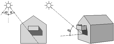
When you select the Consider light setting, the program calculates lights in hidden-line images in accordance with the settings for Light angle in view and Light angle to visible axis. This is not a sun study; the program idealizes the light situation!
Use Light angle in view (left / right) to define the direction of the shadows.
Use Light angle to visible axis (length of shadow) to define how long the shadows are.
|
|
|
alpha: light angle in view, -180° (left) to 180° (right) |
Use Light intensity to specify how many shades of color are used for fills and bitmaps. Enter a value between 1 and 100. The smaller the value, the darker the image.
Use Fill-in light intensity to brighten up shadows and fills. Enter a value between 0 and 100. When you specify an intensity of 0, the fill-in light will not be calculated.
Select Show shadows if you want to display shadows. If you enter negative values for Light angle in view (left / right), the shadows are cast to the left. If you enter positive values, they are cast to the right. The smaller the value, the steeper the shadows. Use Light angle to visible axis (length of shadow) to control how long the shadows are in isometric views. The greater the value, the longer the shadows.
Surfaces
Click the button to open the Set Surfaces palette, where you can assign different colors to element colors. Hidden-line images then use these colors instead of the element colors.
Result
Save
You can save the result in a different drawing file (only available for the ![]() Generate Section tool). Click the Drawing files button to open the Select destination drawing file dialog box. Select an empty drawing file for saving the hidden-line image.
Generate Section tool). Click the Drawing files button to open the Select destination drawing file dialog box. Select an empty drawing file for saving the hidden-line image.
Buttons in the border of the palette
You can find the following tools in the lower border of the palette:
|
(C) ALLPLAN GmbH |
Privacy policy |