![]() Configuration Double Wall: Reinforcement
Configuration Double Wall: Reinforcement
Lattice girder parameters for double walls.
![]() 'Parameters' tab
'Parameters' tab
![]() The Girder leaf is the ... leaf parameter was removed a long time ago. Lattice girders will always be assigned to the invisible leaf; in other words, the invisible leaf is always leaf 1 (which is produced first).
The Girder leaf is the ... leaf parameter was removed a long time ago. Lattice girders will always be assigned to the invisible leaf; in other words, the invisible leaf is always leaf 1 (which is produced first).
If Girder leaf is the invisible leaf is not selected for this parameter in old versions, you must not edit drawing files including double walls with this design in Version 2008. You must create all production data in the version that was used to design the relevant double walls. Otherwise, reinforcement calculations might return incorrect results!
Consider lattice girders:
If this check box is selected, the program considers the bottom boom or top boom when calculating the reinforcement type in accordance with 'as-req.'.
Minimum girder length:
Shorter lattice girders will not be placed.
Round length to:
The rounding value for the lattice girder length.
Rounding option:
Don’t: No rounding.
Exact: 1-4 = round down; 5-9 = round up
Round down: Lengths are rounded down to this value.
Round up: Lengths are rounded up to this value.
Height of anchorage bars [%]:
This setting defines the anchorage bars of the lattice girders. The value is based on a percentage of the girder length up to which the bars are to be installed.
Enter 0 to turn off the function.
Width of anchorage bars:
Width of anchorage bars. Longitudinal bars in this region will be moved.
Spacing between anchorage bars:
Spacing between the individual anchorage bars
![]() "Height option" tab
"Height option" tab
Calculate lattice girders based on:
Option 1: The program calculates the girder height from the wall thickness minus the concrete covers and twice the value of the bar thickness entered, The tolerances specified will be considered.
By using this option, you can control the calculation because the girder heights in the girder catalog are often different from the height between the bottom boom and the top boom.
Option 2: The program calculates the girder height from the wall thickness minus the concrete covers and the actual diameters of the first cross bars. If the cross bars are not in the first layer, the program also considers all diameters of the bars on the outside. The tolerances specified will be considered.
Option 3: The program calculates the girder height from the wall thickness minus the value specified. The program adjusts the concrete cover so that the combination of possible spacers and calculated cross bars is as close as possible to the value specified. As the whole reinforcement must be known so that the program can correctly compute the concrete cover, the calculation opens once again. The tolerances specified will be considered.
Manual selection: The lattice girders are selected manually during the design.
![]() "Limits for height option" tab
"Limits for height option" tab
Round required girder height to cm:
The required lattice girder height is calculated from the wall thickness and other parameters (depending on the selected option). The result of this calculation can be rounded:
Don’t: No rounding.
Exact: 1-4 = round down; 5-9 = round up
Round up: The girder height is rounded up [cm].
Round down: The girder height is rounded down [cm].
Tolerated limits for calculating the height of girders:
Limits for automatically calculating lattice girders based on options 2 and 3. If these limits cannot be met, the program displays a message and the lattice girder will not be installed. In this case, the wall element is marked in accordance with the marking option specified.
![]() "Distribution" tab
"Distribution" tab
Criterion for placing girders:
Criteria for distributing girders for fitted panels:
Two at least: The program always places at least two girders, even for the smallest panels.
Edge offset maintained: The program always uses the edge offset. Consequently, only one girder is used for the smallest panels.
Minimum girder spacing:
Minimum axis spacing for lattice girders that must not be fallen short of.
Edge offset at shorter leaf:
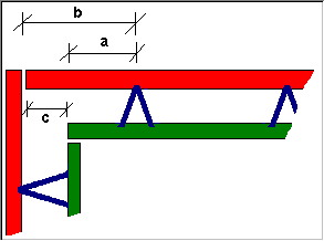
Limit for the minimum offset between the panel edge and the shorter leaf (see illustration, A).
The program tries to use the edge distance defined by the reinforcement type (which is measured from the longer leaf). Whether this or the following parameter has priority depends on which value results in a greater distance from the shorter leaf. The program always complies with this minimum offset so that there is enough space for corner reinforcement.
Edge offset at longer leaf:
Limit for the minimum offset between the panel edge and the longer leaf (see illustration, A).
The program tries to use the edge distance defined by the reinforcement type (which is measured from the longer leaf). Whether this or the previous parameter has priority depends on which value results in a greater distance from the shorter leaf. The program always complies with this minimum offset so that there is enough space for corner reinforcement.
Max. difference for edge offsets:
Maximum offset between the longer leaf and the shorter leaf (see illustration, C). If this value is exceeded and Option 2 is not selected on the Edge offset option tab, the program will take the lattice girder's edge distance from the reinforcement type catalog or reinforcement parameters.
![]() 'Edge offset option' tab
'Edge offset option' tab
Calculate offset to edge of lattice girder based on:
Option 1: The program uses the lattice girder edge offsets on the Distribution tab.
The edge offsets will be ignored when
Option 2: The lattice girder edge offsets on the Distribution tab are always used (even when the distance between the longer leaf and the shorter leaf is greater than the offset to girder edge or the value specified for C on the Distribution tab).
|
(C) ALLPLAN GmbH |
Privacy policy |