![]() Catalogs for precast concrete elements
Catalogs for precast concrete elements
![]() 'General' tab
'General' tab
Created on:
Date the data record was created.
Last modified:
Date the data record was last changed.
Name:
You can enter any name. This name is displayed in the Type list box of the basic parameters for slab element design if the Description box is empty. This way, you can enter a short name for the catalog and a detailed description for the design.
Description:
You can enter any name. This name is displayed in the Type list box of the basic parameters for slab element design.
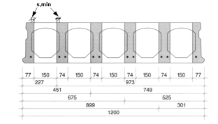
Panel thickness:
The standard value for panel thickness.
Max. panel length:
Maximum value for the panel length. If this value is exceeded during the design process, the program will issue a message.
Longitudinal section / End face section:
Selection box of the joint section catalog. These sections are used for element design. All the edges to which you assign the longitudinal section are given the Smooth edge or Stop position attribute.
To assign this attribute to a panel edge without profiling, you must define a "smooth" section in the joint section catalog and assign it here.
You can use the support conditions to modify the sections applied to the sides of the support. The sections at the joints can be modified using the Modify Parameters, Basic Reinforcement tool.
You can define how sections are displayed and labeled in the configurations.
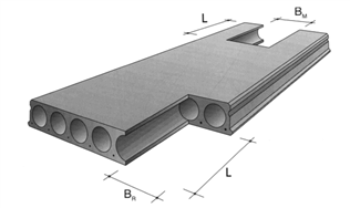
Standard panel width:
The standard value for panel width. This value is used for uncut panels in element design.
Min. fitted panel width:
Minimum value for the panel width. If this value cannot be complied with, the program will create a strip made of in-situ concrete or two fitted panels (depending on your settings).
Max. fitted panel width:
Maximal value for the width of a cut panel. If this value is exceeded, two fitted panels will be created.
Min. offset from cut to web at start/end:
Minimum value for the left/right offset from cuts in areas of hollow blocks to the web. The program uses this entry to calculate the widths of fitted panels and positions of openings.
Opt for cut in axis:
When generating fitted panels, the program attempts to cut the panels in the area of the hollow block axis and to use permissible values for the support widths. If the result is an illegal panel, the minimum offsets from the cuts to the webs are used.
![]() 'Recesses 1' tab
'Recesses 1' tab
Recesses that are larger than the ones defined here can be created using steel headers. The program uses the recess width to define the number of webs that will be cut.
Small recess between two webs:
Maximum length of recesses which are not wider than the space available between two webs.
Medium-sized recesses:
Minimum edge offsets for recesses which are wider than small recesses; however, these recesses do not exceed the limits defined in the Recesses 1 and Recesses 2 tabs.
By defining these minimum offset values, you can prevent non-producible or failure-prone panel webs from being generated as the program extends the recesses to the panel edge. However, these offsets are only used if medium-sized recesses cannot be moved.
This way, recesses at room edges, which result in narrow webs (due to the support) will not be treated as lateral or centered recesses. Rather, these recesses retain their positions.
Using these minimum offset values, you can turn recesses in midspan into support recesses in the head region or into lateral recesses and vice versa.
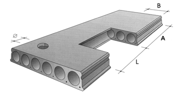
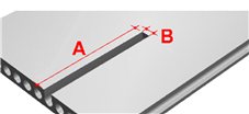
Support recess in corner / head region:
Maximum dimensions for recesses as shown below.
If a displacement is not allowed and if, in the case of recesses in the head region, the edge offset to the longitudinal side is smaller than the minimum offset specified for medium-sized recesses, the program will create a recess in the corner.
Note: The two options cannot be applied to one and the same panel!
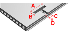
Projecting panels in corner and head regions:
Maximum height:width ratio permitted for projecting panel parts in corner or head regions resulting from support recesses in head regions. The program checks each projecting part. These parts must always be at right angles and parallel to the span direction.
If a projecting part does not meet these criteria, it gets the identifier for the illegal geometry element state. You must then specify how to proceed (e.g. placing mandatory points, …).
![]() 'Recesses 2' tab
'Recesses 2' tab
Recesses that are larger than the ones defined here can be created using steel headers. The program uses the recess width to define the number of webs that will be cut.
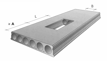
Recess in center of panel:
Maximum dimensions and minimum edge offset for recesses as shown below.
If the minimum edge offset is not complied with and the recess can be moved, the recess will be moved to the offset specified in the design process.
If a displacement is not allowed and the edge offset to the front is larger than the minimum offset specified for medium-sized recesses in the Recesses 1 tab, the program will issue a message during the design calculation process.
If a displacement is not allowed and the edge offsets are smaller than the minimum values specified for medium-sized recesses in the Recesses 1 tab, the program will create a recess in the corner, head or lateral area.
Lateral recess:
Maximum dimensions and minimum edge offset for recesses as shown below.
If the minimum edge offset is not complied with and the recess can be moved, the recess will be moved to the offset specified in the design process.
If a displacement is not allowed and the edge offset to the front is larger than the minimum offset specified for medium-sized recesses in the Recesses 1 tab, the program will issue a message during the design calculation process.
If a displacement is not allowed and the edge offset to the front is smaller than the minimum offset specified for medium-sized recesses in the Recesses 1 tab, the program will create a recess in the corner area.
![]() 'Hollow blocks' tab
'Hollow blocks' tab
Number, type and position of hollow blocks. You can define up to six areas.
Number:
Number of hollow blocks for the current area.
Type:
Selection box of the hollow block catalog.
x-offset, y-offset:
Axis spacing between hollow blocks and the panel edge or the axis of the last hollow block in the x-direction; edge offset from hollow blocks to the bottom panel edge in the y-direction for the current area.
![]() 'Mounting hooks, lifting bolts' tab
'Mounting hooks, lifting bolts' tab
Position
Position of mounting hooks, lifting bolts relative to the panel edges.
The longitudinal sides are defined by the enclosing min-max box parallel to the span direction of the panel. The program thus calculates the longitudinal axes based on the offset in the transverse direction or on the number of the hollow block ribs or hollow blocks. The offset in span direction is measured from the point where the longitudinal axes and the front faces or diagonal cuts intersect.
Example of position of mounting hooks, lifting bolts
Note: The number of rows depends on the element width.
Anchor types:
Type of mounting hook, lifting bolt. You can define up to eight different anchor types depending on the panel weight. The File number and Entry boxes list the fixtures in the Allplan fixture catalog.
![]() 'Insulation' tab
'Insulation' tab
Type
Thickness / Material:
To apply insulation to the bottom side of the panel, enter the Thickness and select the insulation material you want to use in the Material list box.
Note: If you cannot find the required insulation material, the thickness entered differs from the thickness specified for the relevant material in the insulation material catalog.
If the Define dimensions option is selected for the insulation material on the Placement tab, the program places insulating boards. Otherwise, the program creates one insulating board with the dimensions of the precast element.
End faces / Longitudinal sides
You can specify parameters for the concrete supports at the bottom side of the panel. You can make separate settings for end faces and longitudinal sides. The following variants are available: Not used, Concrete pads and Concrete beams. Depending on the variant selected, you can define the following parameters:
Note: The numbers you enter for File no. and Entry must be the same as those in the fixture catalog in Allplan.
The fixture you select for the Concrete pad must be a group fixture that consists of at least one linear fixture with the Interaction with precast element - Positive (merging) setting. This fixture is used to define the outline of the concrete pad in plan. The length of the defined linear component must be the same as the thickness defined for the appropriate insulating layer.
The fixture for the Concrete beam must be a linear fixture with the Interaction with precast element - Positive (merging) setting. This fixture is used to define the outline of the concrete pad in elevation.
![]() 'Bond' tab
'Bond' tab
End faces / Longitudinal sides
You can specify parameters for the recesses at the upper side of the panel. You can make separate settings for end faces and longitudinal sides. The following variants are available: Not used, Fixture and Parameters. Depending on the variant selected, you can define the following parameters:
Note: The numbers you enter for File no. and Entry must be the same as those in the fixture catalog in Allplan.
![]() '->Fact.' tab
'->Fact.' tab
Assignment of entries to factories.
The selected entry applies to the selected factories only. If no factory is selected, the entry applies to all factories.
|
(C) ALLPLAN GmbH |
Privacy policy |