![]()
![]()
|
|
|
SOLID_WALL_X uses the same data structure as SOLID_WALL_B. In addition, you can define more parameters, e.g. for log walls.
Syntax
SOLID_WALL_X left_material, right_material, vertical_material, horizontal_material,
height, x1, x2, x3, x4,
y1, y2, y3, y4,
t, radius
log_height, log_offset,
mask1, mask2, mask3, mask4,
n,
x_start1, y_low1, x_end1, y_high1, frame_shown1,
...
x_startn, y_lown, x_endn, y_highn, frame_shownn,
m,
a1, b1, c1, d1,
...
am, bm, cm, dm
status
Parameters
left_material (string/integer): name/index of left surface
right_material (string/integer): name/index of right surface
vertical_material (string/integer): name/index of vertical surfaces (not supported)
horizontal_material (string/integer): name/index of horizontal surfaces (not supported)
height (decimal): height of wall from its bottom (in Z direction)
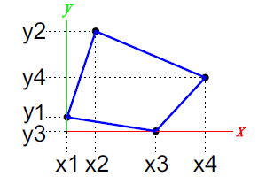
x1, x2, x3, x4 (decimal): wall's end points projected on XY plane
y1, y2, y3, y4 (decimal): wall's end points projected on XY plane
t (decimal): width of wall (in Y direction)
With positive values the wall extrudes to the right of the X axis,
with negative values the wall extrudes to the left of the X axis.
If t=0, the wall is shown as a polygon, and frames are drawn around the openings.
n (integer, ³ 0): number of openings in the wall
x_starti, y_lowi, x_endi, y_highi (decimal): coordinates of wall's opening
m (integer, ³ 0): number of cutting planes
ai, bi, ci, di (decimal): coefficients of the equation defining the cutting plane [ai*x + bi*y + ci*z = di]
Parts on the positive side of the cutting plane will be cut and removed.
Remarks
left_material is used for the whole wall.
The wall's curve consists of segments. Their number is defined by the actual resolution (cf. RADIUS, RESOL and RISE).
Usable since script version 1.1 (Allplan 2012-1).
|
(C) ALLPLAN GmbH |
Privacy policy |