![]()
![]()
|
|
|
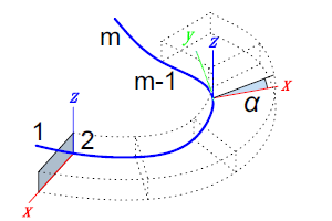
TUBE generates a tubular surface by displacement of a closed polylined contour along a spatial polyline (= path curve). In each joint of the path curve the polylined contour is situated in the bisector plane of the joint segments. At the middle of the path segments the polylined contour is always identical with the polylined contour at the beginning of the displacement (the coordinates u1, w1, ... , un, wn remain unchanged). Arcs and segments can be defined within the polyline by using additional status code values. (See Remarks section for details.)
Syntax
TUBE n, m, mask, u1, w1, s1, ... , un, wn, sn, x1, y1, z1, angle1, ... , xm, ym, zm, anglem
Parameters
n (integer): number of polyline nodes
m (integer): number of path curve nodes
mask: controls the existence of the surfaces at the beginning and the end of the tube (see below)
ui, wi: U and W coordinates of the base polyline nodes in the local U-V-W coordinate system
si (boolean): controls the appearance of the lateral edges; if si = 0 the line segment between ni and ji will not be drawn, if si = 1 this line segment will be drawn
xi, yi, zi: X, Y and Z coordinates of the path curve nodes
Important: The path curve (polyline) comprises two nodes more than the number of generated sections. The first and the last node determine the position in space of the first and the last surface belonging to the tube. These nodes are relevant solely for determining the normal of the surfaces, they are no actual nodes of the path curve. The orientation of the surfaces is the same as that of the surfaces that would be generated at the nodes nearest to the two endpoints, if the tube was continued in the directions indicated by these.
anglei: rotation angle of the cross-section
parameter restrictions: n > 2, m > 3
Masking
mask = j1 + 2*j2
with j1, j2 may be 0 or 1j1 (1): surface at the beginning of the tube is presentj2 (2): surface at the end of the tube is present
Remarks
The polylined contour must be closed. The generating cross-section is not distorted or resized. However, the internal connection surfaces are rotatable about the V axis of the local UVW coordinate system.
The local UVW coordinate system has its origin in the current point with its
V axis is congruent with the tangent of the spatial polyline at the current point (= tangential point)
W axis is perpendicular to the V axis and points upward with respect to the local Z axis (If the V axis is vertical, then the W direction is not correctly defined)
U axis is perpendicular to the VW plane; together they form a right-hand sided Cartesian coordinate system.
For determining a horizontal direction, the W axis in the previous path node is used.
The path curve is a polyline. The resulting tubular surface is a polyhedron.
Usable since script version 1.1 (Allplan 2012-1).
|
(C) ALLPLAN GmbH |
Privacy policy |