![]() Tools: Downstand Beam, Upstand Beam + Upstand + Strip Foundation + Profile Wall
Tools: Downstand Beam, Upstand Beam + Upstand + Strip Foundation + Profile Wall
You can use ![]() Polygonal Component (Inscribed) to draw polygonal components based on the radius of an inscribed circle. You enter polygonal components as you would enter curved components. In addition, you define the number of straight sections that make up the component in the Properties dialog box.
Polygonal Component (Inscribed) to draw polygonal components based on the radius of an inscribed circle. You enter polygonal components as you would enter curved components. In addition, you define the number of straight sections that make up the component in the Properties dialog box.
Inscribed means that the component is based on the radius of an imaginary, inscribed circle. The sections together count as one partial section. The division is a tangent to the circle that you enter when defining the geometric outline.
Difference between inscribed and circumscribed polygonal components
Schematic overview of curved components and polygonal components
To create an inscribed polygonal component
The secant appears.
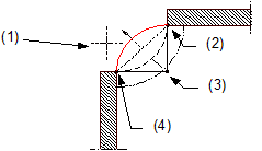
(1) Direction in which the arc is to extend – relative to the secant
(2) Connecting point = end point of component
(3) Center point
(4) Connecting point = starting point of component
The preview shows the direction of extension and the position of the component axis. In the case of multilayer components (for example, walls), you can see the layer structure with the thicknesses of the layers. The position of the first layer gets the number 1, which is the same color as the component axis.
You can change the direction of extension at any time, even while entering components.
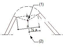
(1) Center of circle
(2) Perpendicular bisector

(1) Proposed center of circle
(2) New center of circle
(3) Crosshairs
Allplan draws the polygonal component.
|
(C) ALLPLAN GmbH |
Privacy policy |