![]() Design (iWall) + Modify Wall Design function
Design (iWall) + Modify Wall Design function
After you have selected the walls, the program divides them vertically and horizontally using the most recent settings. The palette shows the current settings. Adjust the parameters accordingly.
Note that automatically dividing vertical and horizontal joints at the same time while considering the weight (Consider cranes or Maximum element weight) only produces useful results when you use the same height to divide rectangular walls in the view. An inclined top or bottom level of the wall or varying element height leads to completely irregular joints.
The same applies to vertically dividing joints lengthwise in conjunction with an inclined top or bottom level of the wall (with or without considering the weight). Here, too, irregular joints will be produced if the wall is divided horizontally in the inclined area.
In these cases, it is usually better to define the vertical joints manually as mandatory joints right from the start and restrict automatic division to the horizontal direction.
![]() 'Division parameters' tab
'Division parameters' tab
Label
Specify the mark number for the next wall element. If you have selected only one wall, its mark number is entered. Otherwise, the next available number is proposed. You can control how mark numbers are assigned. For example, you can configure the program to begin with 101.
The greatest possible mark number is 99999999.
Options for dividing length
Division option
You can specify how the walls are divided in the vertical direction. Select No division if you want to divide the selected walls only horizontally.
Note: If the program cannot find a solution because you have specified that divisions in openings are not permitted (Division in openings option is not selected), it will display an error message.
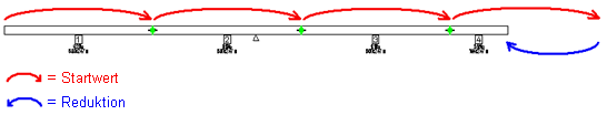
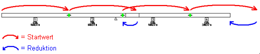
Maximum element length: depending on the visible side specified, the program creates wall elements of maximum possible length in the direction of the wall or in the opposite direction. The starting value for the length of the elements is defined by the value for the Maximum length in the Parameters for dividing length area. By incrementally reducing this starting value, the program ensures that the division criteria (maximum element weight, criteria for openings, ...) are met.
Examples of dividing walls based on maximum element length
Equal element length: divisions are calculated in the same way as for the Maximum element length option. The only difference is that the program uses the "equal element length" for the starting value.
This ”equal element length” is nothing more than the starting value the program uses to calculate the element lengths. Depending on the division criteria specified (maximum element weight, criteria for openings, ...), the actual element lengths can be shorter.
Note: When you divide brick walls, the program preferably searches for wall lengths where the lowest brick row or, in case of a brick offset, the lowest or the brick row above ends with a whole brick, if possible. This generally leads to a reduction in cut and fitted bricks.
Change start point
Mirrored version of a division. As openings and mandatory joints will be considered, the mirrored version can produce a somewhat different result.
Consider Cranes
If you have already defined one or more cranes and their locations using the ![]() Crane Location tool, you can select this option to include the crane parameters in the calculations of the individual panels.
Crane Location tool, you can select this option to include the crane parameters in the calculations of the individual panels.
Joint
Width
Enter the width of the vertical joint. A zero joint is created in the in-situ concrete layer of a double wall or thermal wall.
Connection filter
You can narrow down the entries for section selection. Click ![]() and clear the check boxes of the connections that you want to exclude from the selection menu of the section. The connections that are actually available to you depend on the selected wall type.
and clear the check boxes of the connections that you want to exclude from the selection menu of the section. The connections that are actually available to you depend on the selected wall type.
Section
Select a joint section here that is stored parameterized in the so-called connection files.
Note: The manner in which division joints are formed usually depends on the production plant and can vary from plant to plant. If the default connections do not meet your requirements, you can have them customized to your needs. Please contact your personal sales engineer or our technical support team in Puch.
When you do so, please provide us with a precise sketch defining the joint point by point and the associated layer adjustments. If you want to define the connections yourself in the future, you can also schedule a training session.
Section height / Section thickness / Angle / Edge offset
Offset ...
Angle
Offset...
Shortened layer / Joint offset ...
Layer ... / Offset / Minus...
Shortened layer ...
Depending on the wall type and the selected joint section, you can specify various additional parameters. The program immediately updates the preview of the division to show the effects of your entries.
Symbol fixtures / Linear fixtures / Surface fixtures
These parameters are only available when you can create fixtures for the selected joint section. After you have selected this parameter, you can see the following Symbol fixtures and/or Linear fixtures and/or Surface fixtures areas.
Symbol fixtures / Linear fixtures / Surface fixtures
These areas are only available when you can create fixtures for the selected joint section and the Symbol fixtures and/or Linear fixtures and/or Surface fixtures parameters are selected. Select the respective fixture and specify how to place it.
Fixture
Click ![]() in the right column to
in the right column to ![]() add new fixtures to or
add new fixtures to or ![]() remove existing fixtures from the Fixtures dialog box or to define the parameters of the fixtures in the table.
remove existing fixtures from the Fixtures dialog box or to define the parameters of the fixtures in the table. ![]() and
and ![]() take you from entry to entry.
take you from entry to entry.
Drop-in point
Define the direction of the fixture. Direction ... stands for the individual walls.
Fixture from
Specify whether you want to take the fixture from the Allplan office path, Allplan project path,, Allplan private path, a Manufacturer catalog or an Article catalog. For the first three options, specify the File and Entry, and for the other two options, the Catalog, Class, Subclass, and the required Article.
Depending on the input option for the fixtures in question, you can only choose from symbol fixtures and group fixtures, linear fixtures or surface fixtures. You can also use symbol group fixtures with shaped solids for symbol fixtures.
Distribution option
You can specify whether to place the fixtures From the bottom level, From the top level, or From the middle of the joint height. You also have the Entire joint height option to choose from in the case of linear and symbol fixtures.
Distribution values
You can specify for the three From bottom level, From top level or From middle options whether to enter the values for placing the fixtures as Absolute values or As a % of the joint height. This option is not available for the Full joint heightdistribution option.
Move wall height
You can enter the offset of the first fixture to the reference point specified for the Distribution option. Positive values point in the positive z-direction. This parameter is not available for the Full joint heightdistribution option.
Offset of fixtures
You can enter the offset of the other fixtures to the first fixture. This parameter is not available for the Full joint heightdistribution option.
Move wall thickness
You can use this to move the fixture in the direction of the wall thickness. Positive values point in the positive y-direction.
Length
You must enter the length of the linear or surface fixture here. This parameter is not available for the Full joint heightdistribution option.
Width
Enter the width of the surface fixture here:
Rotation
You can use this to rotate the fixture relative to the zero position. Positive values always point counterclockwise (left turn).
Parameters for dividing length
Minimum length / Maximum length
Shorter or longer elements are not created.
Note: In the case of a brick wall, the length of the brick selected under Material is suggested for the min. length. This value can be overwritten as desired.
Maximum element weight / Maximum element weight
Where required, select the option for Maximum element weight and enter the initial value for the maximum element weight. But you can also define one (or more) crane locations in the drawing. In this case, the program calculates the maximum element weight from the loaded radii. If the resulting weight is less than the value set, division is based on the loaded radii.
Division in openings
Select this option if divisions in openings are permitted. Otherwise, the division point is placed next to the opening by the value specified for Minimum offset to openings.
Round length / rounding value
When you select Division option = Maximum element length as well as the Maximum element weight option and set an initial value for the maximum element weight, you can specify here whether the element length is to be rounded off or not.
If the maximum element weight, the element length for which the Round off length check box is selected will be rounded off in accordance with the specified rounding value.
Options for dividing height
Division option
You can specify how the walls are divided in the horizontal direction. Select No division if you want to divide the selected walls only vertically.
Same height: Starting at the wall base, the program divides the wall in elements of the same height, which you can specify by using the Element height parameter.
If the height of the element at the top is not exactly the Element height specified, the program uses the remaining height to create this element.
Different height: first you need to specify the number of divisions you want to create. Click ![]() to open the table for the Division parameter. You can add more columns by clicking
to open the table for the Division parameter. You can add more columns by clicking ![]() Add. To delete existing columns, select the columns and click
Add. To delete existing columns, select the columns and click ![]() Remove. Specify the Element height.
Remove. Specify the Element height.
Elevation point: Like the Different heights option, you can specify different division heights. Unlike the Different heights option, where the first division height is always measured from the bottom of the wall and the other division heights are then incremented, the Elevation point option always works with absolute heights. Specify the respective elevation point.
If there are several divisions, you can use ![]() and
and ![]() to switch between the columns of the table and change the Element height directly in the dialog box.
to switch between the columns of the table and change the Element height directly in the dialog box.
If the height of the element at the top is not exactly the last height you specified, the program uses the remaining height to create this element. If the sum of the element heights exceeds the wall height, the program only considers the values specified for the current wall height. Here, too, the remaining height is used for the element at the top. This height can differ from the value specified.
Joint section
Select a joint section. The list box contains the joint section catalog's entries that are assigned to the current factory and that can be used with the existing wall thickness.
Width of joint
Enter the width of the horizontal joint.
|
(C) ALLPLAN GmbH |
Privacy policy |