![]() Tools: Wall
Tools: Wall
You can use ![]() Curved Component to draw curved walls. The circle is approximated by a polyline: This results in short, straight segments of linear components, which you can address as a single entity. You can define the number of segments.
Curved Component to draw curved walls. The circle is approximated by a polyline: This results in short, straight segments of linear components, which you can address as a single entity. You can define the number of segments.
Note: Quantity takeoff of curved and circular components is based on the segments.
To create a curved component
The component is attached to the crosshairs. The preview shows the direction of extension and the position of the component axis. The previews of walls are complete with all construction layers and surface elements.
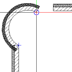
You can change the direction of extension at any time, even while entering components.
Tip: While entering elements, you can quickly change the component axis by means of keyboard shortcuts or ![]() in the dialog line. In the case of walls, you can also change the component axis by means of drag-and-drop editing in the Properties palette.
in the dialog line. In the case of walls, you can also change the component axis by means of drag-and-drop editing in the Properties palette.
The secant and perpendicular bisector of the circle appear in construction-line color; the radius (half the value of the secant relative to the semicircle) is marked with a point symbol.
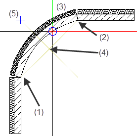
(1) Connecting point = starting point of linear component
(2) Connecting point = end point of linear component
(3) Preview of curved wall is attached to the crosshairs
(4) Center of circle
(5) Point symbol marks the radius on the perpendicular bisector
The system displays half the baseline (secant) as the radius, marked with a point symbol on the perpendicular bisector.
Tip: Click the connecting point (= end point) to create a jointless connection.
Tip: When you have found the radius, you can also click in the workspace - instead of selecting the Enter key - to define the direction in which the curved wall extends.
Allplan draws the curved component.
Note: When you use ![]() Stretch Entities to modify curved components (at wall junctions, for example) while the component axis is hidden, the modifications you make do not affect the axis. As the axis is no longer within the component, this might cause numeric inaccuracies when you dimension the radius of the curved component. When you use
Stretch Entities to modify curved components (at wall junctions, for example) while the component axis is hidden, the modifications you make do not affect the axis. As the axis is no longer within the component, this might cause numeric inaccuracies when you dimension the radius of the curved component. When you use ![]() Stretch Entities while the component axis is visible, curved components behave like circles; that is, the component will be moved.
Stretch Entities while the component axis is visible, curved components behave like circles; that is, the component will be moved.
|
(C) ALLPLAN GmbH |
Privacy policy |