![]() Tool(s): Convert Elements - 3D to U-D elements
Tool(s): Convert Elements - 3D to U-D elements
You can use the User-def. archit. element palette to define how objects you converted to user-defined archit. elements look in plan.
To open the User-def. archit. element palette, double-click a converted user-defined archit. element. As an alternative, right-click the converted user-defined archit. element and select Properties on the shortcut menu.
Tip: Changing the plan views of several converted user-defined architectural elements
“Element” tab
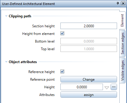
Clipping path
Section height
Define the height at which Allplan cuts the elements for plan view.
You can see a preview of this plane in animation and isomeric view.
Height from element
This option is selected by default. By clearing this option, you can define the section height so that it is below or above the object. Consequently, you can exclude parts of the element from being visible in the section.
Some examples:
Bottom level
Define the height of the bottom level, that is to say, the part of the element Allplan displays as the bottom level.
Top level
Define the height of the top level, that is to say, the part of the element Allplan displays as the top level.
Object attributes
Reference height
This option is not selected by default. When you select this option, you can see the Reference point and Height options and the symbol for the selected Height reference. Based on the reference point, you can attach converted user-defined architectural elements to a default plane, reference surface or reference plane.
Change reference point
Click the Change button to display the reference point of the converted user-defined architectural element as a symbol in construction-line color. To change the reference point, enter values in the dialog line or click in the workspace to define the new reference point.
Note: If you have selected several converted user-defined architectural elements, the Change button is not available for reference points. However, you can change the Height and Height reference; these changes apply to the existing reference points.
Height
Enter the height of the reference point in accordance with the Height reference selected.
Relative height ![]()
![]()
![]()
You can see a symbol that indicates the current height reference. Click this symbol to open the Relative height dialog box and define the reference plane and height reference.
Note: The reference point of a converted user-defined architectural element is attached to a reference plane or an absolute value. Unlike walls, converted user-defined architectural elements cannot stretch between two reference planes. To define the height, you can use the ![]() Relative to lower plane,
Relative to lower plane, ![]() Relative to upper plane and
Relative to upper plane and ![]() Absolute value options.
Absolute value options.
Assign attributes
You can define the attributes of the user-defined architectural element.
Section edges tab
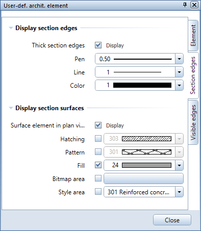
Display section edges
Display section edges with a thick line
You can display the section edges you defined in Clipping path with special format properties or use the format properties of the element.
Pen, line, color
After having selected Display section edges with a thick line, you can define the format properties of the section edges.
Display section surfaces
Display surface element in plan
You can display the section surfaces you defined in Clipping path with a surface element in plan.
Hatching
Select the check box to use Hatching and select the hatching style you want to use.
Pattern
Select the check box to use a Pattern and select the pattern you want to use.
Fill
Select the check box to use a Fill and select the fill you want to use.
If Hatching or Pattern is also active, Allplan places the fill in the background.
Bitmap area
Select the check box to use a Bitmap area and select the bitmap file you want to use.
Style area
Select the check box to use a Style area and select the style area you want to use.
Visible edges tab
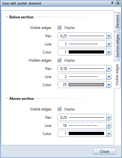
Below section
Display visible edges
Choose to display the visible edges below the section line in plan view and define the format properties you want to use.
Pen, line, color
Define the format properties for the visible edges.
Hidden edges
Choose to display the hidden edges below the section line in plan view and define the format properties you want to use.
Pen, line, color
Define the format properties for the hidden edges.
Above section
Display visible edges
Choose to display the visible edges above the section line in plan view and define the format properties you want to use.
Pen, line, color
Define the format properties for the visible edges.
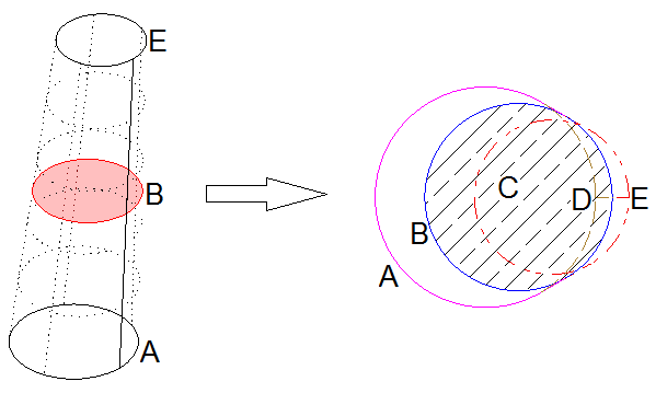
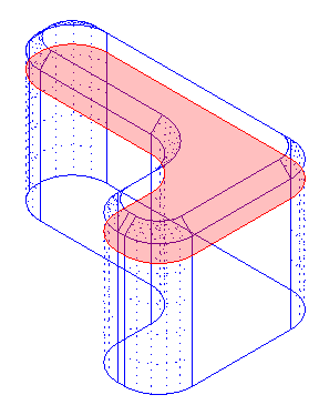
Truncated cone inclined at some angle (column) as a user-defined archit. element:
A Visible edge below section
B Section edge at section height
C Section surface in plan view, with concrete hatching
D Hidden edge below section surface
E Visible edge above section surface
Functions at the bottom
![]() Match parameters
Match parameters
Matches the parameters of a user-def. archit. element clicked, transferring the parameters to the User-def. archit. Element palette.
![]() Load favorite:
Load favorite:
Loads the properties from a favorite file (*.mgkfnfx).
![]() Save as a favorite
Save as a favorite
Saves the properties currently set on all tabs as a favorite file (*.mgkfnfx).
|
(C) ALLPLAN GmbH |
Privacy policy |