![]() Catalogs for precast concrete elements
Catalogs for precast concrete elements
You can use this catalog to define the invoicing parameters and production parameters of a fixture for the programs such as the list generator or NC generator. You can assign this fixture to a CAD fixture in the CAD catalog. The name in the external catalog must agree with the name of the CAD fixture because the program uses this name to link the CAD fixture with the external catalog.
You have the following options to find and sort entries:
![]() "General" tab
"General" tab
created on:
Date the record was created.
Last modified:
Date the record was last changed.
Name:
User-defined name for the fixture. This name is used to link Allplan fixtures with the fixture catalog.
Note: The maximum length for a name is 64 characters. If you enter text that is longer, you will be notified by way of an error message.
ID number:
Some control systems require this reference number. You can enter any number; however, it must be unique.
Fixtures that the program generates automatically (for example, fixing sleeves in the wall program) and that are not entered in this catalog, automatically receive an ID Number between 1 and 10. This ensures that control systems evaluate this number correctly during data transfer. We thus recommend that you start with number 11.
Type:
symbol / linear / surface (Selection box)
Specifies the type of fixture.
Depending on the selected type, some of the following parameters might be invalid and thus not available. To link smart architectural symbols in wall openings and slab openings with the fixture catalog, you must select the surface type.
Use as a smart architectural symbol
This setting is only available for surface fixtures. This setting helps to differentiate normal surface fixtures from surface fixtures for transferring smart architectural symbols to production.
When you select this option, you can define special settings for creating fixture data on the Production tab. In addition, you can make settings on the Smart fixture symbol tab.
When this option is not selected, all settings for using the fixture as a smart architectural symbol are grayed out on the Lists/Schedules, Element plan, and Production tabs.
Assignment:
Panel/Room/Project (selection box)
By assigning the fixture to a room or project, you include the fixture in invoicing but exclude the fixture from the panel (therefore, the fixture does not appear in the element plan). Thus, you can create a list of fixtures that are to be supplied only.
Always convert to wireframe in associative views
This defines how fixtures look in hidden-line images (if Representation - As a wireframe model is not selected in the ![]() Options - Views - Representation - Fixtures). You can thus display specific fixtures as wireframe models while displaying other fixtures as hidden-line images.
Options - Views - Representation - Fixtures). You can thus display specific fixtures as wireframe models while displaying other fixtures as hidden-line images.
Option not selected: The fixture is a hidden-line image.
Option selected: The fixture is a wireframe model so that you can see the fixture better.
Note: If the Representation - As a wireframe model option is selected in the ![]() Options, the setting you make here has no effect. In this case, the program generally converts all fixtures to wireframe models.
Options, the setting you make here has no effect. In this case, the program generally converts all fixtures to wireframe models.
Consider weight:
You can decide whether the program is to consider the weight of the fixture when calculating the element weight. Select the check box to define the weight. You can enter the weight directly or define a formula. Enter the required formula directly or click ![]() to open the Variables for formulas dialog box.
to open the Variables for formulas dialog box.
Make sure that you enter the values for all fixtures (symbol, linear, and surface fixtures) and smart symbols so that the result is always in [kg]!
For example, enter the formula 100*F for a surface fixture with a weight of 100 kg/m².
The element weight of the precast element includes the weight entered or calculated. In addition, the program considers the weight when calculating the center of gravity of the precast element. You can enter a positive or negative number for the weight.
Manufacturer Catalog
Assignment of the fixture to a manufacturer catalog or user catalog. The Manufacturer box must contain a catalog that can be accessed by the CAD system. Manufacturer catalogs and user catalogs have different symbols, making it easier for you to tell them apart. Click ![]() to remove the selected catalog. You can use Class, subclass and Article to define further details.
to remove the selected catalog. You can use Class, subclass and Article to define further details.
When you place a fixture from a manufacturer catalog or user catalog, the program scans the external fixture catalog for a fixture of the type specified (symbol, linear, surface, ...). In addition, the manufacturer, class, subclass, and article (if specified) must match.
You can use the $PT variable in the list text (see "Logging" tab). This outputs the plan text produced by the rule for label styles in the manufacturer catalog or user catalog.
Manufacturer's data:
Full name of manufacturer. Some control systems require this for stock control.
Delivery time:
Delivery time in days. Some control systems require this for stock control.
Job lot:
Packaging unit size. Some control systems require this for stock control.
![]() "Logging" tab
"Logging" tab
List text:
Name of the fixture for the list generator. In most cases, you need to enter a different fixture name for invoicing. Please note that the length is restricted to 80 characters for the analysis on the list generator. You can, however, only see 31 characters on the measurement sheet.
Enter the required text here. In addition to fixed text components, you can also define the List text by means of the Variables for formulas dialog box, which you open by clicking the ![]() button.
button.
Note: Note, however, that these variables can refer to the precast element and not to the fixture. This can result in zero values, which will not be output. Please note as well that not all variables will always be assigned for all special components and modeled objects displayed by fixtures.
Logging
For the Customer and the Factory, you can define different rules for Invoicing, which will be analyzed in the element plan or in lists.
When you select Factory in the standard list for the Fixtures, the program lists only the fixtures with the by: formula setting for Invoicing factory . This might result in an empty list.
by:
Formula / Number|Length|Area
You can choose between the usual logging methods (for example, number for symbol fixtures, length for linear fixtures) and a user-definable logging formula.
Unit:
The program automatically assigns the unit in accordance with the type. If logging is by formula, you can enter an appropriate unit.
Logging formula:
This is only available if logging is by: formula. You can use variables for formulas to control the invoicing quantities in various ways: For example, if you want to calculate panel edge insulation as a surface fixture per meter.
See also: Examples
You can round off the formula result by means of a function that applies to the whole formula. The following options are available:
Syntax: Rounding option ([formula], rounding value); for example, RUP (U,1.0) rounds up the length of a linear fixture to whole meters.
Note: This rounding function always applies to the whole formula! You cannot use this function with terms of a formula! Make sure the syntax is correct: keyword; open parenthesis; formula; comma; rounding value with a dot as a decimal separator; close parenthesis!
![]() "Lists/Schedules"' tab
"Lists/Schedules"' tab
Material number:
The list generator can analyze material numbers as article numbers (for commercial interfaces). If a manufacturer catalog is linked, the article number defined in the relevant manufacturer catalog is used instead of this material number.
Note: You can also define the Material number by means of the Variables for formulas dialog box, which you open by clicking the ![]() button.
button.
Measure
Index for sum sheet:
At the moment the program uses this setting only to control the output sequence in a customer-specific fixture list. The standard lists do not use this setting.
Round off final total:
You can round off the sum of fixtures in the lists (for example, measurement sheet) separately for the Customer and the Factory. You must enter the rounding option (Exact, Round up, Round down) and the rounding value.
Balance rounded amount with elements:
When you round off the final total, it no longer matches the sum of the individual items listed by the single panel schedule. So you can balance the items as follows:
Stagger smart symbols by size:
This setting is only available for surface fixtures for which you have selected the Use as a smart architectural symbol option on the General tab. You can use this setting to automatically output special openings in stagger levels in some lists. These special openings include wall openings, shuttering boards, and so on, which you have entered as smart symbols.
However, this definition has an effect only when the fixture is linked with a smart opening symbol in Allplan. By default, the Recess fixture is linked with all wall openings.
This setting has an effect on the following lists:
Slab measurement sheet
xml-KPR slab interface
ADS_KSTP slab interface
Wall measurement sheet
xml-KPR wall interface
ADS_KSTP wall interface
xml-ADS interface
PXML Delegate interface
Suppress output of article:
This option is only available when you have selected As a recess or As a smart symbol for staggering smart symbols by size. The smart symbol is usually listed as a fixture in the measurement sheet or transferred to the ADS interfaces. Select this option if you do not want to list the smart symbol as a separate fixture.
As a result, the program counts the smart symbol as a recess, listing it with the recesses only.
Name for staggering:
This setting is only available when you have selected As a smart symbol for staggering smart symbols by size. You can enter a name for the stagger level. If you do not enter anything, the program uses the reference name of the fixture.
Output smart architectural symbols
Define whether and with which text you want to output the labels of slab openings and wall openings with smart architectural symbols in lists.
Specify whether the opening size, opening depth, and selected unit are included in labels. The Unit and the number of Decimal places are based on the settings on the Element plan 2 tab.
Note: Labels of rectangular openings that the program rotates before placing (for example, diamonds) include the length and width of the rotated rectangle. The program interprets the longer side of the rectangle as the length and the shorter side as the width.
![]() 'Element plan 1' tab
'Element plan 1' tab
The following settings apply only to element plans.
Fixtures:
Show fixtures
Select the Show fixtures check box and choose the views in which you want to display the fixtures. You can also choose to display mark numbers together with the fixtures. You have the following options for generating mark numbers. You can always enter a Prefix, regardless of the option you choose:
If you place fixtures with different settings for the mark number in a precast element, the program first assigns the mark number defined to the fixtures with the fixed setting. The program then assigns the free mark numbers to the fixtures for which you selected the priority setting. Finally, the fixtures with the Automatically setting get a mark number.
For the Prefix, enter a fixed text or click ![]() to open the Formula editor, where you can define an attribute or a formula. You can use the formula editor as usual. A single attribute is represented by @[number]@ in the box. A formula expression requires escape characters, that is to say, the formula is enclosed by <![formula]!> (For example: <!PARENTPRECAST(@1461@)!> .
to open the Formula editor, where you can define an attribute or a formula. You can use the formula editor as usual. A single attribute is represented by @[number]@ in the box. A formula expression requires escape characters, that is to say, the formula is enclosed by <![formula]!> (For example: <!PARENTPRECAST(@1461@)!> .
Note: If you want to change the attribute or formula, we recommend selecting the attribute or formula (including the angle brackets) beforehand.
Table
Label in table:
Select the Label in table check box and specify which text you want to use to label the fixtures in the table.
Maximum text length:
You can limit the maximum number of characters for labels in the table (before the program adds quantities). The program initializes existing entries with 64.
Complete invoice quantity:
Define how the table in the element plan outputs the invoice quantity specified on the Logging tab. In the case of symbol fixtures, you can make this definition only if the by: formula setting is selected for at least one of the rules for Invoicing. You can choose not to add the invoice quantity to the label (no setting) or to add the invoice quantity in accordance with the settings for Invoicing customer or Invoicing factory.
If logging is not by Formula, the program adds the default quantity of the fixture; that is, the length in [m] for linear fixtures and the area of the polygon in [m2] for surface fixtures. In the case of symbol fixtures, the program does not add the number of pieces.
Dimensioning
Match dimension line index from attributes:
If you have deactivated this option, you can define the dimension line index for symbol fixtures. This will then be used in the element plan and will affect the table, display and dimensioning in the element plan.
Attention: The Dimension line index catalog entry will not change an existing Dimension string index attribute on the fixture. Analyses (such as in the formula editor) using the Dimension string index attribute will remain unchanged.
Horizontal dimensions/Vertical dimensions:
Define how you want to dimension fixtures in element plans. You can define separate settings for horizontal dimension lines and vertical dimension lines. By defining the settings accordingly, you can dimension fixtures in a view or section independently of the general setting for vertical and horizontal dimension lines on the Dimension lines tab in the Properties of a view or section. You can select the following dimensioning types:
Note: If the program creates a common dimension line for different fixtures having the same Dim. string index but different dimensioning settings in the fixture catalog, the program uses the most frequently used setting.
Dimension smart symbol:
You can use this option to specify for an individual smart symbol that it will appear on a separate dimension line, even though you have chosen the Dimension together option in the Geometry group of the Dimensions tab for smart symbols in the Layout Catalog. In normal circumstances, the setting is the new option according to the Layout Catalog.
Note: Please note that if the Use smart symbol names option is selected in the Layout Catalog under More settings in the Geometry group of the Dimensioning tab, a separate dimension line will in any case be created for each smart symbol with a different name. Where applicable, please select an appropriate combination here.
Points to dimension:
In the case of symbol fixtures, you can opt for the circumscribed rectangle to be dimensioned in the element plan in place of the defined point(s) to dimension.
To do this, select the Min-max points option in the selection dialog box for points to dimension.
![]() 'Element plan 2' tab
'Element plan 2' tab
Label smart architectural symbols
Specify here for surface fixtures whether and how to label wall openings and slab openings with smart architectural symbols in the table.
Specify under Add smart symbol label whether the opening size, opening depth, and selected unit are included in labels. You can make separate settings for the views and the table. Define the Unit and the number of Decimal places.
Note: Labels of rectangular openings that the program rotates before placing (for example, diamonds) include the length and width of the rotated rectangle. The program interprets the longer side of the rectangle as the length and the shorter side as the width.
![]() "Classification" tab
"Classification" tab
You can assign a Category and a Type to the fixture. The categories and types are predefined, making sure that the fixtures are consistent.
Note: The categories listed correspond to the IFC4 classes currently defined for fixtures by buildingSMART.
These settings apply when you export the precast elements by using the new IFC export tool in the Report & Production Data Manager module in TIIM. The program uses the Category of the fixture to define the IFC class (for example, IfcCableCarrierSegement). The Type of the fixture will be exported as the MountingPartType attribute in the separate IFC4precast_MountingPartCommon PropertySet. The user-defined type will be exported as the additional MountingPartUserType attribute. Fixtures without a category will be exported as the IfcDiscreteAccessory IFC class.
Category
Select a category for the fixture and click the ![]() button. The selected category appears in the line.
button. The selected category appears in the line.
Note: You cannot click the ![]() button until you have selected an entry that is subordinate to a category. Otherwise, the button is not available.
button until you have selected an entry that is subordinate to a category. Otherwise, the button is not available.
To change an entry, select the new entry and click the ![]() button again. By clicking the
button again. By clicking the ![]() button, you can completely delete an entry.
button, you can completely delete an entry.
type
You can select the user defined and *virtual type in addition to the predefined types and the not defined type.
After selecting the user-defined type, you can see the additional Custom text box, where you can enter any text for the type.
The *virtual setting is for fixtures that are only intended to be defined as auxiliary objects, for example, and are not intended to be considered in TIM Report Manager for the IFC export for precast elements.
Note: The *virtual setting is of importance if there is a group fixture involved (such as an ISO cage) containing certain objects to be displayed on the element plan (such as hatching areas, etc.) or to provide guidance during installation (such as directional arrows, etc.).
![]() "Production" tab
"Production" tab
These settings apply when you create production data directly from Allplan by means of the ![]() Production Data, NC Generator tool.
Production Data, NC Generator tool.
The program displays only the parameters that are appropriate to the fixture type (symbol, linear, or surface).
CAD-CAM interfaces (Unitechnik, PXML)
Create fixture data:
Select No if you do not want to produce the fixture. If you do not transfer a fixture to the production file, you can still use it to control formwork attributes applied to panel edges or recess edges.
Select In both leaves if you want to add fixtures intended for multilayer walls (double walls and thermal walls, not possible with sandwich walls) to the production data of the second leaf even if the fixtures are only in the leaf that will be produced first. The program uses this setting only for real fixtures, which means that this setting does not apply to insulating layers, concrete areas, tiles, smart symbols, and so on.
The program provides different settings for surface fixtures for which you have selected the Use as a smart architectural symbol option on the General tab. By means of these settings, you can produce the fixture leaf by leaf.
For symbol fixtures and surface fixtures, you can select the Compress geodetic data option to compress the geodetic data of appropriate fixtures (connecting elements, insulating boards, and tiles) for transfer to production.
Switch the substitute symbol to 1 point so that the program creates production data for connecting elements in the same way as production data for insulating boards and tiles.
Remove CUTOUT data block:
You can remove the CUTOUT data block of the Unitechnik file leaf by leaf from surface fixtures for which you have selected the Use as a smart architectural symbol option on the General tab. Removing this block means that if the fixture and a recess are congruent, the recess will be removed. This is required for smart architectural symbols if you add a steel frame or wooden frame, for example. In this case, the fixture serves as permanent formwork.
If the file contained a fixture in addition to the CUTOUT block, the formwork robot would place formwork you would have to remove manually afterward.
Note: However, some control systems require the CUTOUT block to control the concrete spreader (otherwise, concrete would be poured into the opening). In this case, do not remove the CUTOUT block. You can use the "special formwork" attribute to configure the formwork robot not to place formwork.
Substitute symbol
Symbol size:
The program transfers the symbol fixture as a substitute symbol with the dimensions specified in Symbol size or with its actual geometry from the CAD system. When you select the Calculate maximum extents option, the program computes the size of the substitute symbol based on the actual extents of the fixture's smart symbol foil (from the corresponding view in the CAD system).
In the case of surface fixtures and smart architectural symbols, the program uses the Substitute symbol selected for recesses as the fixture geometry in the production data (Unitechnik + PXML) of the actual polygon.
Note: You can find smart symbols both in the formwork data (CONTOUR and CUTOUT) and in the fixture data. If the plotter plots the formwork data, select the Remove CUTOUT data block option.
Like walls (Recess fixture), slabs can be given a default fixture, which will then be used for all recesses. For hollow core elements and prestressed hollow core elements, the Name of this fixture must be "HDrecess"; for other slabs, the Name must be "slab recess".
This function is only available for real surface fixtures and smart architectural symbols. It is not available for special parts created with iWalls, such as concrete areas, concrete strips, surfaces, insulating boards, upstands, tiles, and so on.
Set formwork attributes:
You can specify how linear fixtures or surface fixtures affect formwork attributes of panel edges or recess edges that are exactly the same size and shape as the fixture edges. This applies to the geometry data in the CONTOUR and CUTOUT blocks of the Unitechnik file.
Click ![]() to tell the program how to handle line attributes:
to tell the program how to handle line attributes:
When you select the In path only option, the program uses only the panel edge that has exactly the same size and the same shape as the path of the outline for shaped fixtures.
In addition, TIM also uses the definitions of the formwork attributes to model chamfers or fillets into the geometry exported to IFC for the following types of precast elements:
Modeling is based on the Chamfer width defined in the Factory catalog or the Fillet radius, parameters defined for the precast element, and fixtures in the precast element. When you create the NTF file, Allplan includes these parameters and uses them to calculate the chamfer or fillets for IFC export. Which edges of a precast element get chamfers or fillets depends on the definitions of the formwork attributes for the precast element and on the definitions of the formwork attributes made here. For the iWall, you define the formwork attributes on the Attributes tab of the parameters of the design mode.
Note: It is not always possible to compute chamfers or fillets, in particular with modelings by other tools (for example, profile definitions, ...).
Should you have any questions, please contact our technical support team.
Include projection:
Fixtures projecting beyond the enclosing rectangle of the element outline enlarge the enclosing rectangle of this element. As a result, you must increase the maximum element dimensions and include a corresponding offset in the outline data.
By selecting the Top level, Bottom level, and Lateral options, you can choose to consider the projection for the bottom level, top level, and the sides. When you select the Element thickness option, you can increase the element thickness in the NC generator if the fixture projects beyond the element thickness.
However, fixture geometries that exceed the maximum panel dimensions cannot be produced in compliance with the interface specifications (Unitechnik CAD-CAM). Therefore, the fixture geometries will be clipped accordingly. Clear the Clip geometry of fixture check box if you do not want to use the clipping feature. In this case, make sure that the control system can process the data.
Additional information
Free info line 1/2:
Free info lines 1 and 2 for Unitechnik CAD-CAM interface V 6.0 and later (20 characters each).
Note: You can also define the Free info line by means of the Variables for formulas dialog box, which you open by clicking the ![]() button.
button.
Type and code:
For production (Unitechnik) - see interface definition from control system.
Bar projection:
Special parameter for pallet loading on control system.
![]() "Smart fixture symbol" tab
"Smart fixture symbol" tab
The settings on this tab are only available for surface fixtures for which you have selected the Use as a smart architectural symbol option on the General tab.
You can insert smart architectural symbols into wall openings. When you define a surface fixture for a smart architectural symbol, you can configure the program to automatically add "notional" linear fixtures to the opening edges for analyses in the table of the element plan, for invoicing, or for transferring data to production.
Note: As these "notional" linear fixtures are not real fixtures, you cannot modify them in placing drawings or in the windows of the ![]() Element Plan and
Element Plan and ![]() Edit Element tools.
Edit Element tools.
Create fixtures at edges of smart symbol
Select a linear fixture from the fixture catalog for each edge. The directions (Left edge, Right edge, Top level, and Bottom level) are based on the zero position (defined position) of the precast element and not on the position for production!
The program uses just a few settings from the fixture catalog when analyzing these temporary, linear fixtures in reports and element plans. These settings are the entries for List text on the Logging tab and the entries for Label in table on the Element plan tab. Note the following restrictions:
Note: As these temporary fixtures are not real fixtures, the program does not write mark numbers to the drawing and to the table in the element plan!
When creating production data, the edge attributes of the linear fixtures for CONTOUR or CUTOUT on the Production tab of the fixture catalog have priority over the edge attribute of the superordinate smart symbol.
The settings for Consider projection are irrelevant! The parameters for Additional information will be transferred.
![]() "Concrete areas" tab
"Concrete areas" tab
Please note the following settings only apply to symbol fixtures in walls created using iWall for which the creation of hollow blocks can be selected.
Create concrete areas in hollow blocks:
No: Concrete areas are not created for the selected fixture.
Yes: Concrete areas are created around the selected fixture with the following settings.
Top, bottom, left and right:
You can define the dimensions of the concrete area to be created around the fixture.
Note: The values specified always refer to the reference point of the fixture (e.g. the midpoint on an e-socket).
Create concrete areas only when fixture touches hollow block:
No: Concrete areas are always created for the selected fixture.
Yes: Concrete areas are only created in a hollow block if the min-max box of the fixture touches one of the two sides of a hollow block next to the rib.
Create concrete areas only on side where fixture touches hollow block:
This option is only released if the previous Create concrete areas only when fixture touches hollow block option is set to Yes.
No: The concrete area is always created on both sides of the rib.
Yes: The concrete area is only created on the side of the rib on which the Min-Max Box of the fixture touches the hollow block.
![]() "Reinforcement" tab
"Reinforcement" tab
In the case of attached or loose basic reinforcement, these settings apply to all element types (slabs, walls created using ![]() Design and
Design and ![]() Design (iWall)). Please note these settings only apply to smart symbols in the case of secondary bars for attached or loose reinforcement.
Design (iWall)). Please note these settings only apply to smart symbols in the case of secondary bars for attached or loose reinforcement.
Note: For walls created using ![]() Design (iWall), the reinforcement will also be cut open if the fixture is located merely in the reinforcement area but not in the concrete cover zone. For all other design modes, the fixtures are only considered for cutting if are located in the concrete cover zone.
Design (iWall), the reinforcement will also be cut open if the fixture is located merely in the reinforcement area but not in the concrete cover zone. For all other design modes, the fixtures are only considered for cutting if are located in the concrete cover zone.
If you want to use the same settings for both sides, clear the Separate setting for visible side/top check box in the Invisible side/bottom area. As a result, you cannot make settings in the Visible side/top area on this tab and on the Replace reinf. tab.
Visible side/top or Invisible side/bottom
Longitudinal bars, cross bars / Cut secondary reinforcement (for smart symbols only):
When selected, the program tries to place the bars around this fixture. If this is not possible, the bars will be cut.
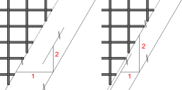
Offset parallel to span direction / perpendicular to span direction:
By means of these two parameters, the program creates a min-max box around the recess (fixture). At inclined recess edges, the program checks the maximum offset for the bars in span direction and transverse to span direction. The program uses the maximum offset to cut the bars of both directions and the secondary bars at the resulting edge.
Left illustration: Offset 1 > offset 2 ![]() offset 1 is used for cutting.
offset 1 is used for cutting.
Right illustration: Offset 1 < offset 2 ![]() offset 2 is used for cutting.
offset 2 is used for cutting.
Note: In the case of attached reinforcement, the bars for which the required projection is no longer complied with (this results in invalid welding points with the perpendicular bar) will still be shortened if this option is selected in the configurations.
Cut automatic lattice girder:
When selected, the program tries to place the automatically generated lattice girders around this fixture. If this is not possible, the lattice girders will be cut.
Note: Please note the way secondary and shear girders behave is controlled by the settings for the secondary reinforcement.
Distance to automatic lattice girder:
Enter the offset to the automatically generated lattice girder.
Replace reinforcement:
You can specify whether and how you want to replace longitudinal bars and cross bars that are cut by fixtures. Note, however, that reinforcement can only be replaced in MWS meshes (that is, attached reinforcement). Cut secondary bars and lattice girders will not be replaced.
Assembly bars:
Define whether to create assembly bars for surface fixtures for which the Use as a smart architectural symbol option is selected on the General tab and the Cut longit. bars, cross bars option is selected on this tab. This definition overrides the setting in the Assembly bars configuration entry in the configurations for attached reinforcement. If this setting is not available, the program always creates the assembly bars Acc. to configuration.
Fixture is mandatory point for grid:
For symbol fixtures, you can define the fixture as the mandatory point for attached reinforcement in the 0° or 90° direction.
Cut symbol fixtures:
This setting applies to loose reinforcement and attached reinforcement in slabs and to walls created by means of ![]() Design and
Design and ![]() Design (iWall).
Design (iWall).
![]() "Replace reinf." tab
"Replace reinf." tab
You can define structural reinforcement when the Cut longit. bars, cross bars option and the Structural option for attached reinforcement are selected on the Reinforcement tab. You can specify separate settings for the visible/top and invisible/bottom sides and for the longitudinal and transverse directions.
For the Steel grade, you can use the steel grade of the basic reinforcement (Like default setting) or a steel grade defined in the Steel grade catalog.
You can create the reinforcement up To the edge or place it with the anchorage length lo (Automatic) or the Anchorage length specified.
![]() "->Assignment" tab
"->Assignment" tab
Assignment of entries to components.
The selected entry applies to the selected components only. If no component is selected, the entry applies to all components.
![]() "->Fact." tab
"->Fact." tab
Assignment of entries to factories.
The selected entry applies to the selected factories only. If no factory is selected, the entry applies to all factories.
|
(C) ALLPLAN GmbH |
Privacy policy |