![]() Tools: Hidden-Line Image
Tools: Hidden-Line Image
You can use this palette to specify how Allplan calculates hidden-line images.
Note: Hidden-line images in destination documents differ from the Hidden view type in viewports: To define parameters for the Hidden view type, point to this view type and click ![]() .
.
Note: The settings in the Hidden-Line Image in Destination Document palette and in the Settings for Hidden-Line Images dialog box of the associative views are mutually dependent.
Display
Formats
Click the button to open the Formats palette, where you can define settings for the hidden-line image.
Surface elements
No surface elements
With this setting, surface elements are not visible in hidden-line images.
Only fills from colors
With this setting, fills represent surface elements in hidden-line images. The element color defines the fill color. If a surface is assigned, the surface color of the corresponding 3D element defines the fill color. Any textures are ignored.
Create bitmaps from textures, fills from colors
With this setting, surface elements with textures are represented by bitmap areas in hidden-line images. Fills are applied to surfaces without textures (the fill color is derived from the element color or surface color).
Note: Bitmap areas are resized (cropped) correctly only in parallel projections (elevation and isometric views). But you can also achieve realistic images in perspective views with granular surfaces such as sand or plaster.
Consider transparency
Use Consider transparency to display surfaces to which you have assigned transparent surfaces as transparent so that hidden surfaces become visible. This parameter is only available when you have selected the Only fills from colors or Create bitmaps from textures, fills from colors setting.
Consider light
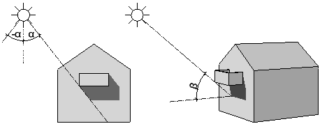
When you select the Consider light setting, the program calculates lights in hidden-line images in accordance with the settings for Light angle in view and Light angle to visible axis. This is not a sun study; the program idealizes the light situation!
Use Light angle in view (left / right) to define the direction of the shadows.
Use Light angle to visible axis (length of shadow) to define how long the shadows are.
|
|
|
alpha: light angle in view, -180° (left) to 180° (right) |
Use Light intensity to specify how many shades of color are used for fills and bitmaps. Enter a value 1 through 100 here. The smaller the value, the darker the image.
Use Fill-in light intensity to brighten up shadows and fills. Enter a value 0 through 100 here. When you specify an intensity of 0, the fill-in light is not calculated.
Select Show shadows if you want to display shadows. If you enter negative values for Light angle in view (left / right), the shadows are cast to the left. If you enter positive values, they are cast to the right. The smaller the value, the steeper the shadows. Use Light angle to visible axis (length of shadow) to control how long the shadows are in isometric views. The greater the value, the longer the shadows.
Surfaces
Click the button to open the Set Surfaces palette, where you can assign different colors to element colors. Allplan will then display the new colors - instead of the element colors - in the hidden-line image.
Calculate reinforcement
When you select the Calculate reinforcement setting, the program converts reinforcing bars and meshes into design entities when calculating the hidden-line image. When this setting is not selected, the program ignores the reinforcement.
Buttons in the border of the palette
You can find the following tools at the bottom of the palette:
|
(C) ALLPLAN GmbH |
Privacy policy |