![]() Tools: Strip Foundation
Tools: Strip Foundation
Clicking ![]() Properties opens the dialog box for entering parameters and attributes for strip foundations.
Properties opens the dialog box for entering parameters and attributes for strip foundations.
You can change the settings in the dialog box before you create or while you are creating the component. Previews show the input options you have.
Shape of cross-section
Note: You can only use rectangular cross-sections for curved and spline-based components.
![]() Rectangular
Rectangular
Click ![]() to select a rectangular outline.
to select a rectangular outline.
![]() Stepped
Stepped
Click ![]() to create a foundation with a stepped cross-section.
to create a foundation with a stepped cross-section.
![]() Beveled at top
Beveled at top
Click ![]() to create a foundation with a cross-section beveled at the top.
to create a foundation with a cross-section beveled at the top.
![]() Beveled at bottom
Beveled at bottom
Click ![]() to create a foundation with a cross-section beveled at the bottom.
to create a foundation with a cross-section beveled at the bottom.
![]() Section
Section
Click ![]() to select a profile saved as a symbol in the Library palette. Allplan displays the symbol name and shows the profile with its dimensions in the preview.
to select a profile saved as a symbol in the Library palette. Allplan displays the symbol name and shows the profile with its dimensions in the preview.
You can also ![]() Mirror or
Mirror or ![]() Rotate the profile.
Rotate the profile.
Note: You can change the dimensions of the profile (cross-section) by entering values for the Thickness and Height in the Parameters, attributes area.
Modification mode
This area is only available when you modify components by selecting ![]() Apply Archit. Component Properties or Properties on the shortcut menu (based on initial settings).
Apply Archit. Component Properties or Properties on the shortcut menu (based on initial settings).
Axis
Centered below wall
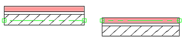
When you select the Centered below wall option and enter or ![]() Match the thickness of the wall, Allplan automatically calculates the position of the axis. To enter the strip foundation, click the corners of the wall.
Match the thickness of the wall, Allplan automatically calculates the position of the axis. To enter the strip foundation, click the corners of the wall.
Preview, position of component axis
A schematic representation of the component including the selected format properties and surface settings is shown here. In addition, you can position the component axis by dragging or entering values.
Position
In this column, you can use icons to position the axis in the component.
Parameters, attributes
Height column
Here, you can see the height of the component. Click in the column to change it.
Click in the Height column to define the height of a component or construction layer. You can define the height as an absolute value. You can also define the height of the component based on a default reference plane, custom reference plane, offset plane, reference surface or based on an existing component.
Height of foundation top based on component bottom: ![]()
Format properties
![]() Pen,
Pen, ![]() Line,
Line, ![]() Color
Color
You can define the format properties for the strip foundation.
Note: The properties in the Properties palette have no effect on the strip foundation; the settings you make here apply.
You can assign custom surfaces to components. You can also modify surfaces you have already assigned. These surfaces are visible in viewports of the Animation view type.
Surfaces
Show surface element in plan
When you select this option, the selected surface element appears not only in sections but also in plan view.
Catalog assignment, material selection button
Options for component axis and profile
Click to open the ![]() Options directly in the Component axis and Component profile areas. When you create a component with a section saved as a symbol, you can define the Number of segments in the Component profile area by entering a value between 8 and 360; the default setting is 36.
Options directly in the Component axis and Component profile areas. When you create a component with a section saved as a symbol, you can define the Number of segments in the Component profile area by entering a value between 8 and 360; the default setting is 36.
![]() Save favorite file (expanded dialog box only)
Save favorite file (expanded dialog box only)
QuickSelect favorites
Click the arrow on the right side to open a list with the 20 favorites you used last.
![]() Match parameters
Match parameters
You can copy the parameters from an existing component. The parameters are entered in the dialog box and you can modify them.
|
(C) ALLPLAN GmbH |
Privacy policy |