![]()
![]()
|
|
|
Both the ![]() Architecture role and the
Architecture role and the ![]() Engineering role contain the new Structural framing task with the Structural Framing Objects task area. This task area contains the new axis grid that was introduced with Allplan 2019 and the new
Engineering role contain the new Structural framing task with the Structural Framing Objects task area. This task area contains the new axis grid that was introduced with Allplan 2019 and the new ![]() Structural Framing Column and
Structural Framing Column and ![]() Structural Framing Beam tools.
Structural Framing Beam tools.
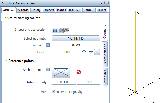
Structural framing column
On the Geometry tab, you can define the cross-section of the column by choosing a rectangular or circular shape or taking any profile from the library. Allplan rotates the cross-section about the reference point. This is also the point that Allplan uses to create the column.
You can define the height of the column in the familiar “Height” dialog box.
To define the position of the reference point, you select the anchor point and enter the distances between these two points in the x-direction and y-direction. You can also choose to place the anchor point in the center of gravity. After you have placed the column, you can see the reference point in construction-line color at the lower end of the column.
If you want, you can also display the axis in construction-line color in the center of gravity of the cross-section.
On the two other tabs - Representation and Attributes - you can define format properties, surface elements and settings for analyzing structural framing objects as you would do this for architectural elements.
By clicking ![]() Match parameters in the lower border of the palette, you can take the parameters from an existing column. You can save all the settings of the column by selecting
Match parameters in the lower border of the palette, you can take the parameters from an existing column. You can save all the settings of the column by selecting ![]() Save as a favorite and retrieve the settings by selecting
Save as a favorite and retrieve the settings by selecting ![]() Load favorite.
Load favorite.
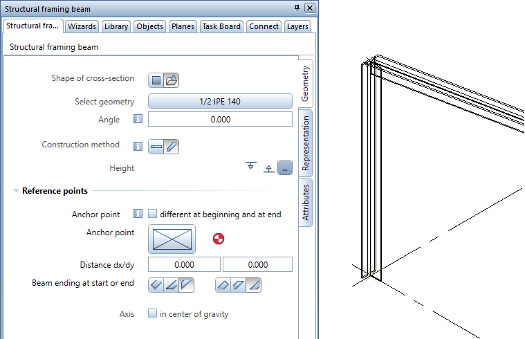
Structural framing beam
On the Geometry tab, you can define the cross-section of the beam by choosing a rectangular shape or taking any profile from the library. Allplan rotates the beam about the line that connects the reference points. These are also the points that Allplan uses to create the beam.
To define the construction method of the beam, you can choose between ![]() horizontal and
horizontal and ![]() inclined. Horizontal beams and inclined beams differ in the possible number of reference points and how these reference points take their height settings from planes.
inclined. Horizontal beams and inclined beams differ in the possible number of reference points and how these reference points take their height settings from planes.
To define the position of a reference point, you select the anchor point and enter the distances between these two points in the x-direction and y-direction. You can also choose to place the anchor point in the center of gravity. After you have placed the beam, you can see the reference points in construction-line color at the start and end of the beam.
For both ends of the beam, you can choose to create a perpendicular, horizontal or vertical end. If you want, you can also display the axis in construction-line color in the center of gravity of the cross-section.
On the two other tabs - Representation and Attributes - you can define format properties, surface elements and settings for analyzing structural framing objects as you would do this for architectural elements.
By clicking ![]() Match parameters in the lower border of the palette, you can take the parameters from an existing beam. You can save all the settings of the beam by selecting
Match parameters in the lower border of the palette, you can take the parameters from an existing beam. You can save all the settings of the beam by selecting ![]() Save as a favorite and retrieve the settings by selecting
Save as a favorite and retrieve the settings by selecting ![]() Load favorite.
Load favorite.
|
(C) ALLPLAN GmbH |
Privacy policy |