Associative dimensioning
Dimensioning in Allplan has already been associative to a certain extent: Reference point and dimension line point were linked. When you selected the reference point while changing an element or component, Allplan also updated the dimension line. By selecting  Match, you could take the height from an opening and add this height to the dimension line. When the opening height changed, you had to use
  Modify Component Height, Additional Text to add the new height to the dimension line.
The new type of associative dimensioning is linked directly with the dimensioned object. When you change the object, the dimension line adapts immediately without you having to pay attention to reference points.
The following tools use the new type of associative dimensioning:
 Dimension Line (horizontal, vertical, angle or direct)
 Block Dimension Line
 Elevation Point
 Pegging Out
 Reference Line Dimensioning
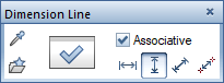
To turn on associative dimensioning in Allplan, open a tool that creates dimension lines and select the Associative check box on the Dimension Line Context toolbar.
Dimension the element or component as usual; some special features make your work easier:
- The reference point is linked with the element or component and the dimension line point.
Tip: To see the reference points all the time, open the  Options on the Dimension line page, go to the Representation area and select the Highlight reference points option.
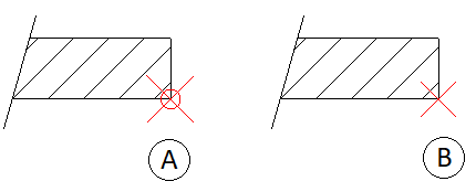
Figure: reference points with associative dimensioning (A) and without associative dimensioning (B)
- Point to a point that you want to dimension.
- If the point is unique, click it.
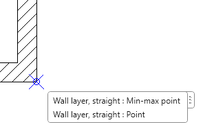
- When you point to a component edge or wall corner, Allplan might find several points that can be dimensioned. In this case, a ToolTip lists the possible points.
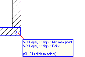
- Select Shift while clicking to open a list, where you can click the required point.
- When you dimension an opening and click the first point, Allplan reads the sill height and opening height from the model, displaying these values as a preview in the dimension line. Use the context toolbar to define whether you want to display these values. Allplan inserts these values in the dimension line when you click the second point of the opening.
- When a room adjoins the component, Allplan considers the height of the finish floor surface when calculating the sill height and opening height. Room and model can be in different drawing files; the drawing files can even be open in reference mode. The only requirement is that the Consider floor surfaces of rooms when calculating the sill height option is selected in the Associativity area on the Dimension Line page in the Options.
Note: The Consider floor surfaces of rooms when calculating the sill height option applies to the current project. - A door opening belongs to the room to which the opening direction points (door swing symbol). This is particularly important for rooms with different floor structures.
- Dimension line and component can be in different drawing files. The components that you want to dimension can even be in reference drawing files.
- Whenever you change the geometry of the component and opening, Allplan updates the dimension line immediately even if the dimension line is in a reference drawing file.