Mesh Element with DTM
 Task area Terrain Model
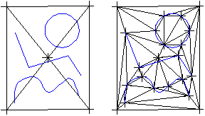
You can use this tool to mesh an element’s control points - or the points where it intersects with existing grid lines - with a DTM.
To mesh an element with a digital terrain model
- Click
 Mesh Element with DTM (How).
 - Click the DTM.
- Use the input options to specify which points you want to mesh with the DTM:
- Grid: meshes the points of intersection between the element and the existing grid lines with the DTM.
- Poly: meshes the element’s control points.
- IntPol: meshes the element’s control points. However, interpolation is not at the height of the terrain but between the start and end point of the points located on the element.
- 36: specifies the number of segments in a circle for polygonization of curves.
Notes:
- The height of the points meshed is interpolated to terrain height (except the IntPol option).
- In the case of 3D solids, all the corners visible in plan are used as control points.
- Special lines (e.g., cutaways) can now be positioned directly to ensure that the elements pass through the grid points.