![]()
![]()
|
|
|
![]() Task area Terrain Model
Task area Terrain Model
You can also use several profiles (even from different DTMs) in an extract.
Several identical profiles in an extract
You can display the original status, planning, and spoil status of a terrain in an extract in order to measure the differences in area, for example. To do this, create a profile section for each DTM with an identical clipping line (for example, by using the same bearer element each time). Activate all the drawing files and select the relevant clipping lines.
Example of a longitudinal profile with several horizons:
Section: AAA
AAA: A = 10.84 m2; xS = 3.11 m BBB: A = 10.37 m2; xS = 3.15 m |
|
A Reference height B Centers of gravity C Actual level D Planned level E Profile F Reference line G Station H Height lines without skew |
Several different profiles in an extract
What is important when creating the profile sections is the stationing of the individual profiles. For the profile section to be displayed without breaks, the end station of the first profile section must match the start station of the second profile section.
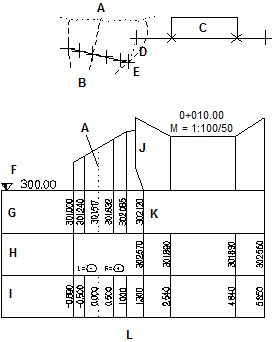
For example: Activating a transverse profile and a longitudinal profile
The end station of the first (transverse) profile is 1.3 m. Consequently, the first station of the second (longitudinal) profile must also be 1.3. Therefore, the second element must be a composite element as a station origin can only be defined here.
|
A Axis B Transverse profile 1 C Longitudinal profile D Station at 1.3 m E Distance of 1.3 m |
F Reference height G Height H Longitudinal I Station J Skew K Summing up the horizons with consecutive stations L Height lines without skew |
|
(C) ALLPLAN GmbH |
Privacy policy |